Rotary electric machine
- Summary
- Abstract
- Description
- Claims
- Application Information
AI Technical Summary
Benefits of technology
Problems solved by technology
Method used
Image
Examples
first embodiment
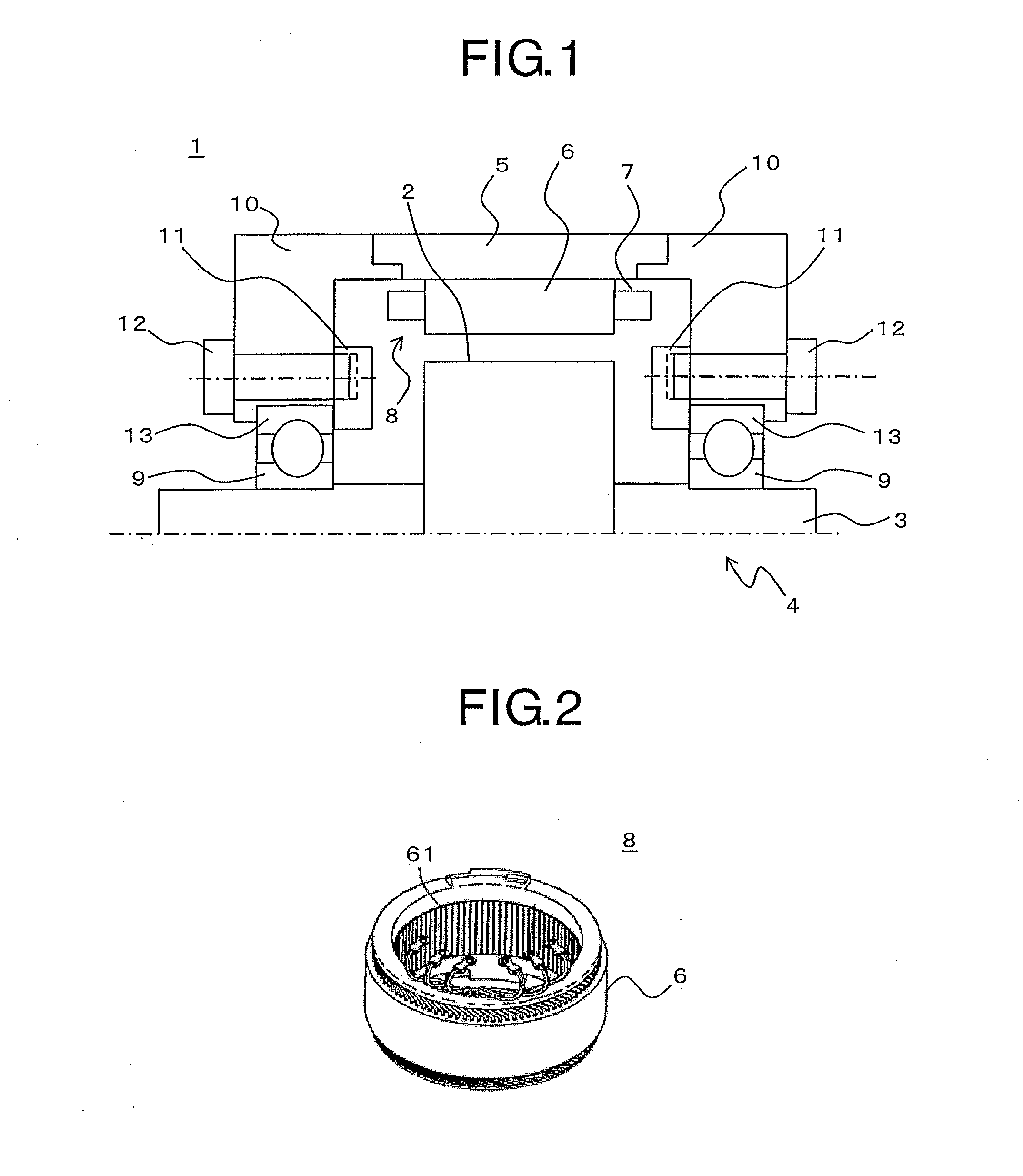
[0067]FIG. 1 is a sectional view of an upper half part of a rotary electric machine according to a first embodiment of the present invention including a shaft thereof. In FIG. 1, a rotary electric machine 1 includes a field pole rotor 4 including a magnetic body 2 serving as a rotor core and a shaft 3, a stator 8 including a stator core 6 fixed to a frame 5 and a coil 7 mounted to the stator core 6, a bearing 9, a bracket 10, a bearing fixing screw 12 for fixing an endplate 11, and the endplate 11 for fixing a side surface of a bearing outer race 13.
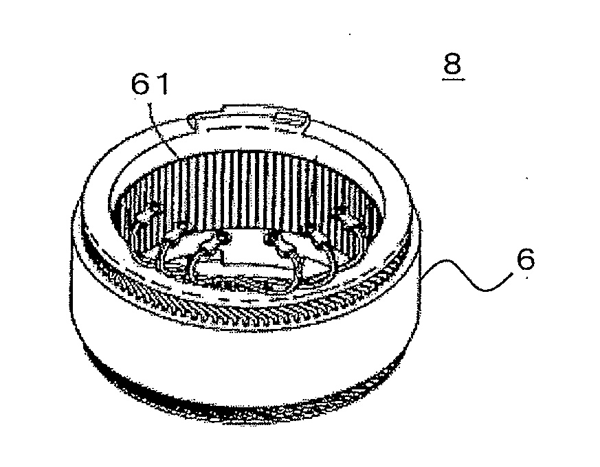
[0068]FIG. 2 is a perspective view illustrating the stator 8 taken out from the rotary electric machine 1 illustrated in FIG. 1. In FIG. 2, the stator 8 includes the stator core 6 formed by stacking thin steel plates in an overlapping state, and the coil 7 mounted to a plurality of slots 61 extending in a central axis direction, which are provided in a circumferential direction at predetermined pitches so as to be opened to an inner peri...
second embodiment
[0254]FIG. 31 is a structural view illustrating a stator core before a wave winding is mounted according to a second embodiment of the present invention. Further, FIG. 32 is a structural view illustrating the stator core after the wave winding is mounted and the stator core is welded in the second embodiment of the present invention.
[0255]In FIG. 31, the stator core 6 of the above-mentioned first embodiment is divided at one position in the arc circumferential direction to have a linear shape. After the wave winding and the insulating member are mounted in the slots 61 of the stator core 6, the stator core 6 is rolled to bring end surfaces of the stator core 6 into abutment to each other, and then the end surfaces are welded. Thus, the circular stator core 6 of FIG. 32 is formed.
[0256]FIG. 33 is a plan view illustrating a state of the coil before the wave winding is mounted to the stator core in the second embodiment of the present invention. In FIG. 33, in order to provide the coil...
third embodiment
[0258]FIG. 34 is a schematic diagram illustrating a division state of a wave winding in a third embodiment of the present invention, when viewed from the axial end portion of the stator. FIG. 34 illustrates a case where each wave winding of the stator of the above-mentioned first embodiment is divided into four parts, and the numbers of slots of the division units are Q1, Q2, Q3, and Q4, respectively. Further, the number of series turns in the Qn slots (n is a positive integer) Nn is Qn×(the number of series conductor wires) / 2.
[0259]In this case, the number of slots has relationships of Q1=Q3 and Q2=Q4, and by setting the same number of series conductor wires with respect to the corresponding number of slots, the number of series turns with respect to the corresponding number of slots has relationships of N1=N3 and N2=N4.
[0260]Therefore, parts having the same number of series turns corresponding to the number of slots in which the divided wave winding is provided are arranged so as ...
PUM
 Abstract
Description
Claims
Application Information
 - R&D
- Intellectual Property
- Life Sciences
- Materials
- Tech Scout
- Unparalleled Data Quality
- Higher Quality Content
- 60% Fewer Hallucinations
Browse by: Latest US Patents, China's latest patents, Technical Efficacy Thesaurus, Application Domain, Technology Topic, Popular Technical Reports.
© 2025 PatSnap. All rights reserved.Legal|Privacy policy|Modern Slavery Act Transparency Statement|Sitemap|About US| Contact US: help@patsnap.com


