Power source apparatus

Active Publication Date: 2013-07-25
SANYO ELECTRIC CO LTD
View PDF4 Cites 15 Cited by
  • Summary
  • Abstract
  • Description
  • Claims
  • Application Information

AI Technical Summary

Benefits of technology

The power source apparatus described in this patent allows for accurate current detection with a shunt resistor without changing metal plate dimensions. It achieves this by using interval adjustment structures in the current flow terminals connected in series with the batteries to adjust the distance between the attachment points of the current flow terminals. This controls the current distribution within the metal plate shunt resistor and adjusts the voltage induced across the voltage detection terminals. The power source apparatus also has the characteristic of adjusting the ratio of the metal plate shunt resistor's width to the distance between the current flow terminals, allowing for efficient adjustment of the voltage induced across the voltage detection terminals. It also has the characteristic of allowing easy connection of circuitry to detect the voltage induced across the shunt resistor voltage detection terminals. Additionally, it has the characteristic of accurately detecting battery capacity and controlling battery charging and discharging to prolong battery life.

Problems solved by technology

Batteries have the characteristic that they degrade significantly due to over-charging and over-discharging.
However, accurate detection of the battery current is critical for actual implementation.
This is because battery current detection error results in battery remaining capacity error.
In particular, since remaining capacity is computed from the integral of the current, current detection error can accumulate over time and remaining capacity error can gradually increases over time.
In addition, wasted power proportional to the square of the current is consumed by the shunt resistor, and Joule heating occurs as a result of that power consumption.
However, even when the metal plate material is fabricated to have constant dimensions between the voltage detection terminals, processing variation results in electrical resistance error.
Electrical resistance error due to processing variation causes error in the induced voltage, which in turn results in error in the detected current.
However, these techniques post-process shunt resistors manufactured in quantity to adjust their shapes, and consequently have the drawback that electrical resistance cannot be adjusted in a simple manner.

Method used


Image

  • Power source apparatus
  • Power source apparatus
  • Power source apparatus

Examples


Embodiment Construction

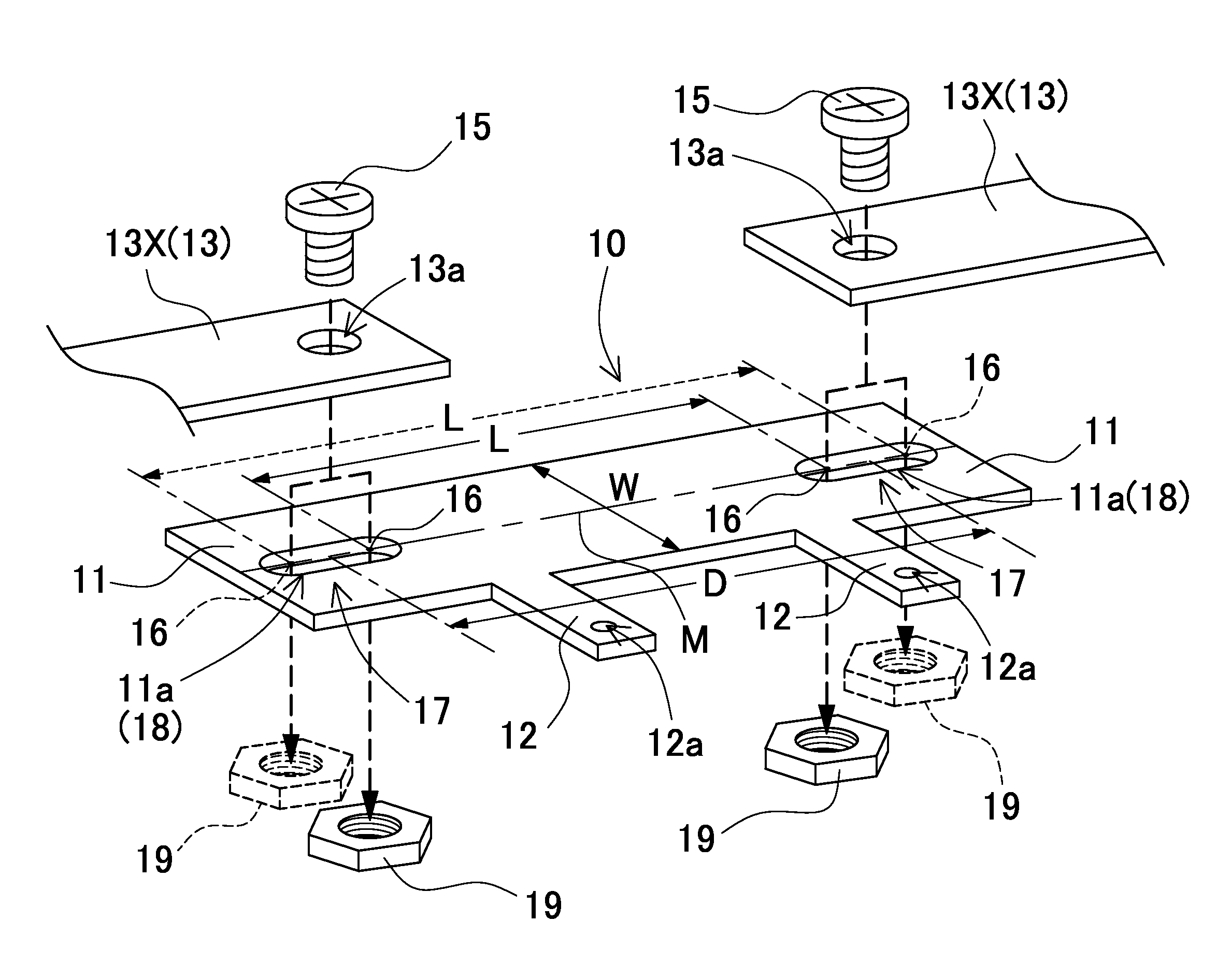
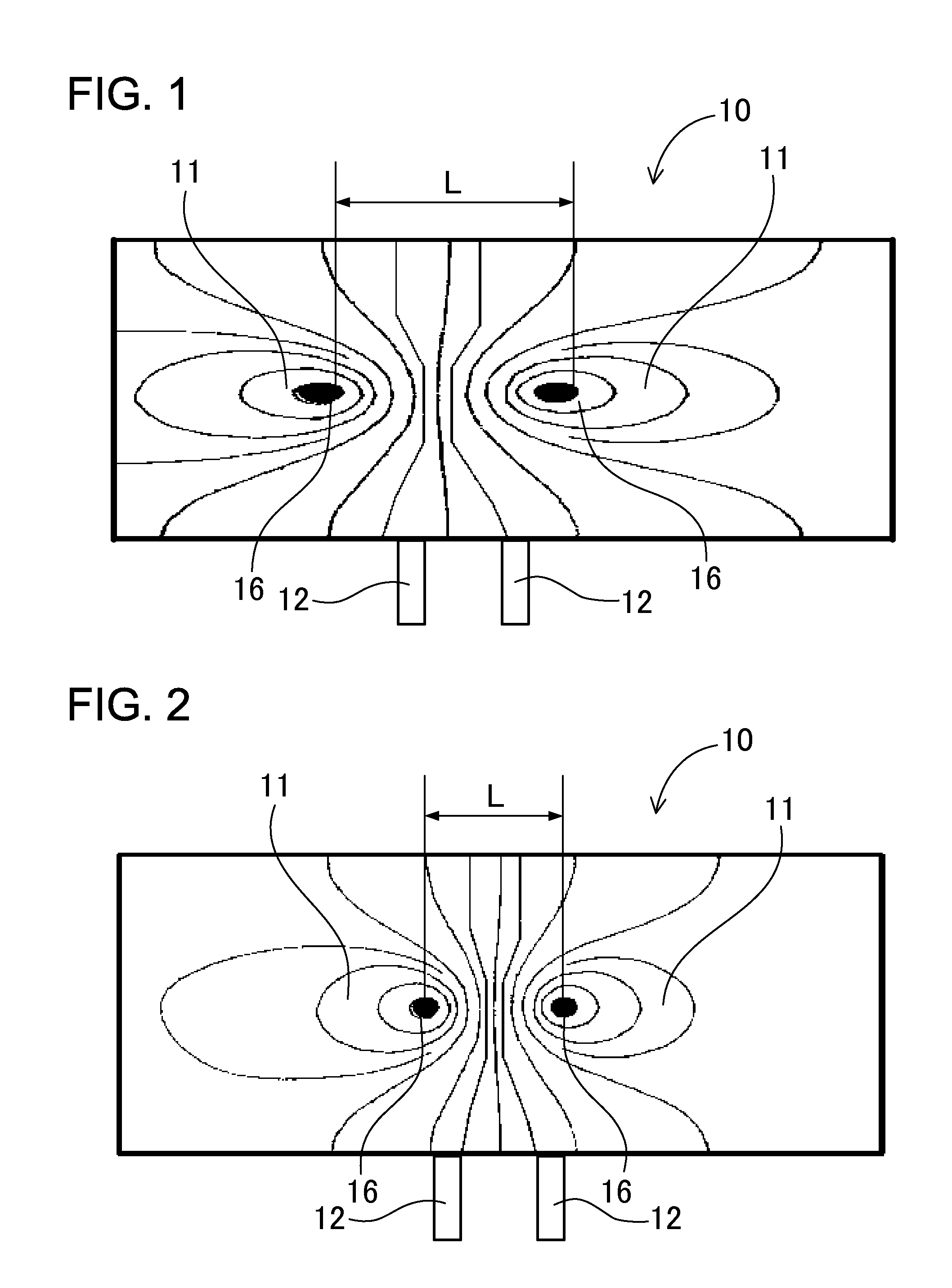
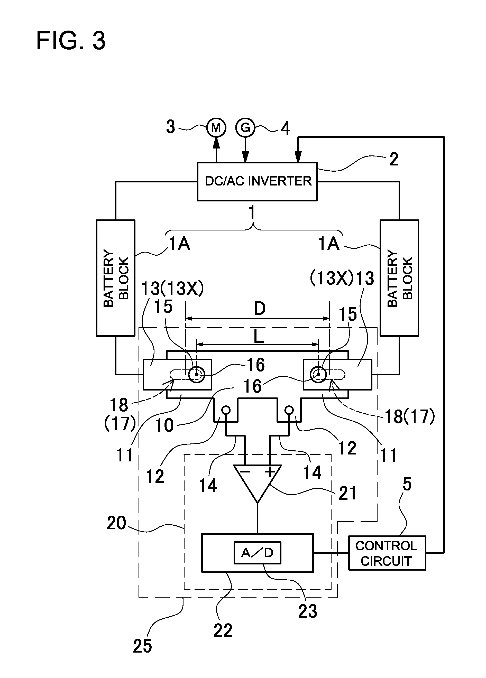
[0026]The following describes embodiments of the present invention based on the figures. However, the following embodiments are merely specific examples of a power source apparatus representative of the technology associated with the present invention, and the power source apparatus of the present invention is not limited to the embodiments described below. Further, components cited in the claims are in no way limited to the components indicated in the embodiments.

[0027]Turning to FIG. 3, a vehicle power source apparatus carried on-board a hybrid vehicle (hybrid car, hybrid electric vehicle, HEV) or plug-in hybrid vehicle (PHV, plug-in hybrid electric vehicle, PHEV) is shown. However, the power source apparatus of the present invention can be used in any application charged and discharged with high current and is not limited only to automotive applications such as in a hybrid vehicle. The power source apparatus of the figure is provided with batteries 1 that supply power through a d...


PUM


Abstract

The power source apparatus is provided with a shunt resistor connected in series with batteries, and a current computation circuit that detects the voltage induced by current flow through the shunt resistor to compute battery current. The shunt resistor is provided with a pair of current flow terminals at two separated points on a metal plate connected in series with the batteries via connecting leads, and a pair of voltage detection terminals on a side of the metal plate between the pair of current flow terminals. Further, the shunt resistor has interval adjustment structures to adjust the distance (L) between attachment points where the connecting leads attach to the pair of current flow terminals. The distance (L) between lead attachment points is adjusted with the interval adjustment structures to finely adjust the voltage induced at the voltage detection terminals due to current flow between the two attachment points.

Description

BACKGROUND OF THE INVENTION[0001]1. Field of the Invention[0002]The present invention relates to a power source apparatus having a shunt resistor connected in series with the batteries to determine battery current by detecting the voltage induced across the resistor, and in particular to a power source apparatus optimally suited as a power source that is charged and discharged with high current such as a power source that supplies power to a motor to drive a vehicle.[0003]2. Description of the Related Art[0004]A power source apparatus is equipped with current sensing to detect battery charging and discharging current. A power source apparatus with a current sensor can integrate current to compute remaining capacity, can control battery charging and discharging using the computed remaining capacity, and can prevent battery over-charging and over-discharging. Batteries have the characteristic that they degrade significantly due to over-charging and over-discharging. Accordingly, accur...

Claims


Application Information

Patent Timeline
IPC IPC(8): H02P23/14H01M50/569
CPCG01R1/203G01R31/3696H02P23/14H01M2200/108H01M10/4285H01M10/48H01M2200/103H01M10/425G01R31/364Y02E60/10H01M50/569
Inventor YUGOU, MASAKINAKANO, SHINYA
Owner SANYO ELECTRIC CO LTD
Why Eureka
Try Eureka