Transmission-line transformer in which signal efficiency is maximised

a transmission line transformer and signal efficiency technology, applied in fixed transformers, mutual inductances, printed inductances, etc., can solve the problems of power loss generation in the conventional transmission line transformer, and achieve the effects of increasing signal efficiency, parasitic capacitance components, and increasing coupling factors

Active Publication Date: 2013-07-25
FOUND OF SOONGSIL UNIV IND COOP
View PDF7 Cites 3 Cited by
  • Summary
  • Abstract
  • Description
  • Claims
  • Application Information

AI Technical Summary

Benefits of technology

[0010]According to a transmission line transformer having increased signal efficiency of the present invention, a coupling factor may be increased as an area of a first transmission line and areas of second and third transmission lines, which face each other, are increased, and parasitic capacitance components generated between the first through third transmission lines and a semiconductor substrate may be decreased by using the second and third transmission lines, which have narrower widths than the first transmission line, as a secondary transmission line is divided into two regions. In addition, an economic effect of reduced manufacturing costs may be obtained since areas occupied by the first transmission lines may be decreased by 50% or more compared to when all transmission lines are disposed at same heights from a semiconductor substrate.

Problems solved by technology

However, the areas may be increased by increasing lengths of the primary and secondary transmission lines 110 and 120, but a power loss may be generated in the conventional transmission line transformer due to parasitic resistance components of the metal lines generated accordingly.

Method used


Image

  • Transmission-line transformer in which signal efficiency is maximised
  • Transmission-line transformer in which signal efficiency is maximised
  • Transmission-line transformer in which signal efficiency is maximised

Examples


Embodiment Construction

Technical Problem

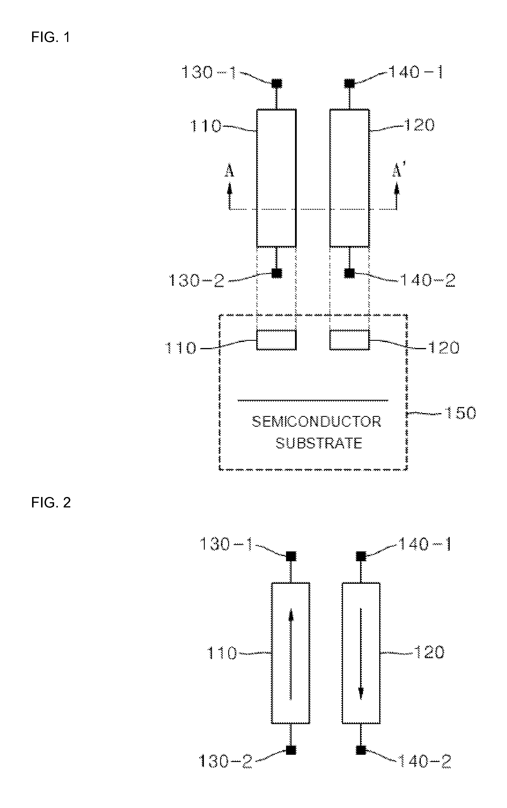
[0008]The present invention provides a transmission line transformer capable of improving a coupling factor by increasing an area of a primary transmission line and an area of a secondary transmission line facing each other while decreasing a signal power loss caused by a semiconductor substrate.

Technical Solution

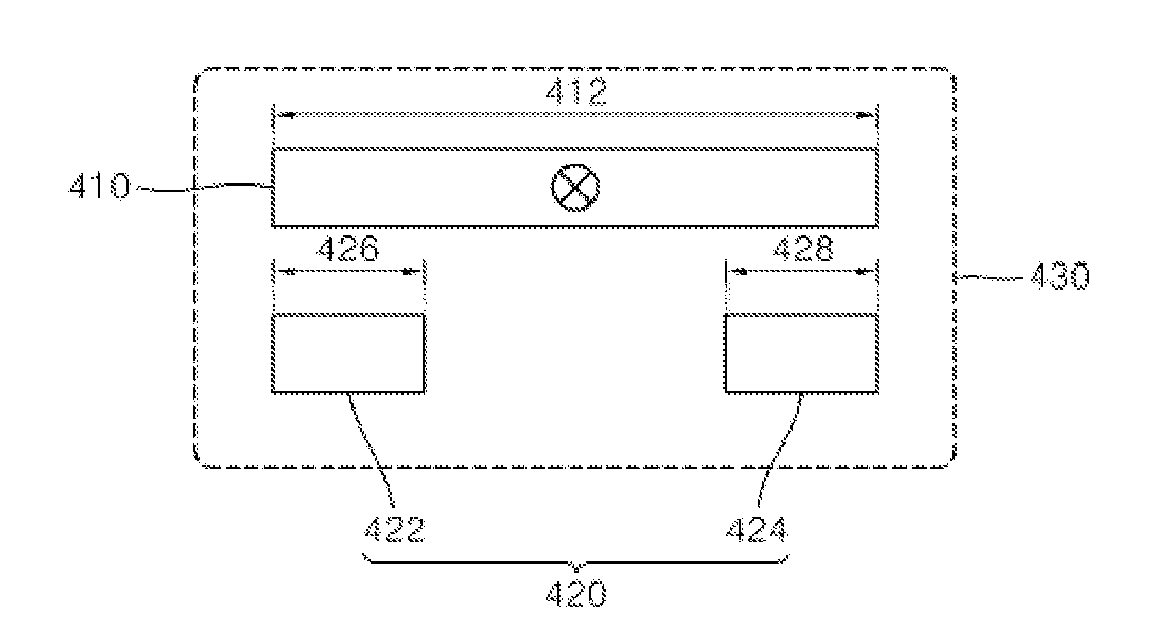
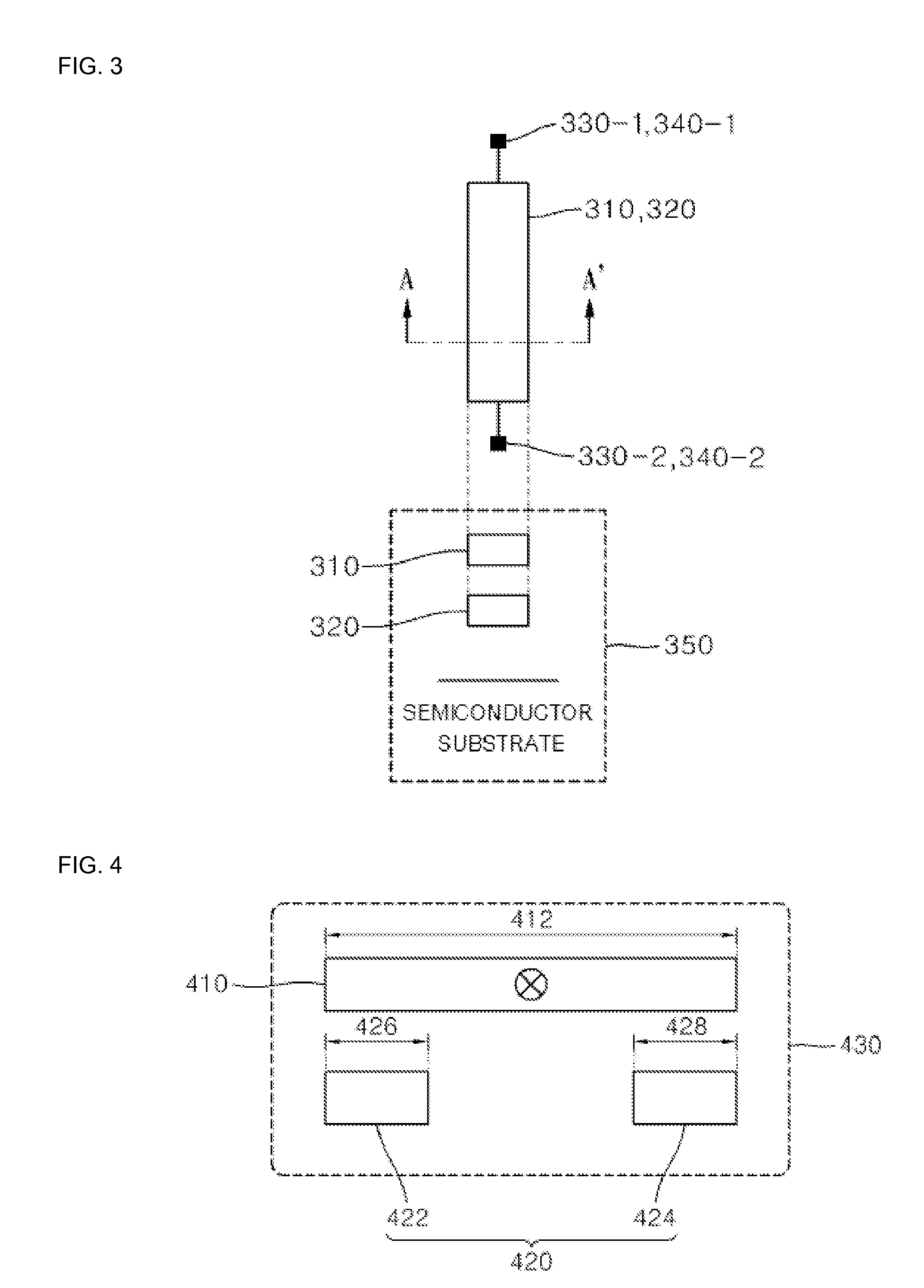
[0009]According to an aspect of the present invention, there is provided a transmission line transformer formed on an integrated circuit (IC), the transmission line transformer including: a first transmission line disposed in one direction; and second and third transmission lines having same length direction as the first transmission line and spaced apart from each other in a lateral direction above or below the first transmission line.

Advantageous Effects

[0010]According to a transmission line transformer having increased signal efficiency of the present invention, a coupling factor may be increased as an area of a first transmission line and areas of secon...


PUM

PropertyMeasurementUnit
lengthaaaaaaaaaa
widthaaaaaaaaaa
strengthaaaaaaaaaa

Abstract

Provided is a transmission line transformer having increased signal efficiency. The transmission line transformer is formed on an integrated circuit (IC), wherein a first transmission line disposed in one direction. Second and third transmission lines have same length direction as the first transmission line and are spaced apart from each other in a lateral direction above or below the first transmission line. Accordingly, an area of the first transmission line and areas of the second and third transmission lines, which face each other, are increased, thereby improving a coupling factor. Also, since a secondary transmission line is divided into two regions and uses the second and third transmission lines that have narrower widths than the first transmission line, parasitic capacitance components generated between the first through third transmission lines and a semiconductor substrate may be decreased.

Description

TECHNICAL FIELD[0001]The present invention relates to a transmission line transformer having increased signal efficiency, and more particularly, to a transmission line transformer formed on a semiconductor substrate in a high-frequency integrated circuit (IC) and whose signal efficiency is increased by improving a coupling factor.BACKGROUND ART[0002]A transformer that is one of common devices used in a high-frequency integrated circuit (IC) for a wireless communication system is used to convert impedance or combine electric powers. FIG. 1 is a diagram of a conventional transmission line transformer, wherein a primary transmission line 110 and a secondary transmission line 120 are formed on a semiconductor substrate. Also, primary ports 130-1 and 130-2 are connected to each end of the primary transmission line 110 and secondary ports 140-1 and 140-2 are connected to each end of the secondary transmission line 120. Referring to a cross-sectional view 150 taken along a line A-A′ of FIG...

Claims


Application Information

Patent Timeline
Patent Type & Authority Applications(United States)
IPC IPC(8): H01F17/00
CPCH01P5/10H01P5/04H01F17/0006H01P5/12H01F19/00
Inventor PARK, JONG HOONPARK, CHANG KUN
Owner FOUND OF SOONGSIL UNIV IND COOP
Why Eureka
Try Eureka