
Switching amplifier and control method therefor

a switching amplifier and control method technology, applied in the direction of amplifiers, low-frequency amplifiers, semiconductor devices/discharge tubes, etc., can solve the problems of reducing the efficiency of switching amplifiers, limiting the achievement of a sufficiently broad bandwidth, and reducing the efficiency of signal amplification, so as to reduce noise and reduce conduction loss , the effect of increasing the reliability of switching amplifiers

Inactive Publication Date: 2016-04-07
PS TECH CO LTD
View PDF2 Cites 2 Cited by
  • Summary
  • Abstract
  • Description
  • Claims
  • Application Information

AI Technical Summary

Benefits of technology

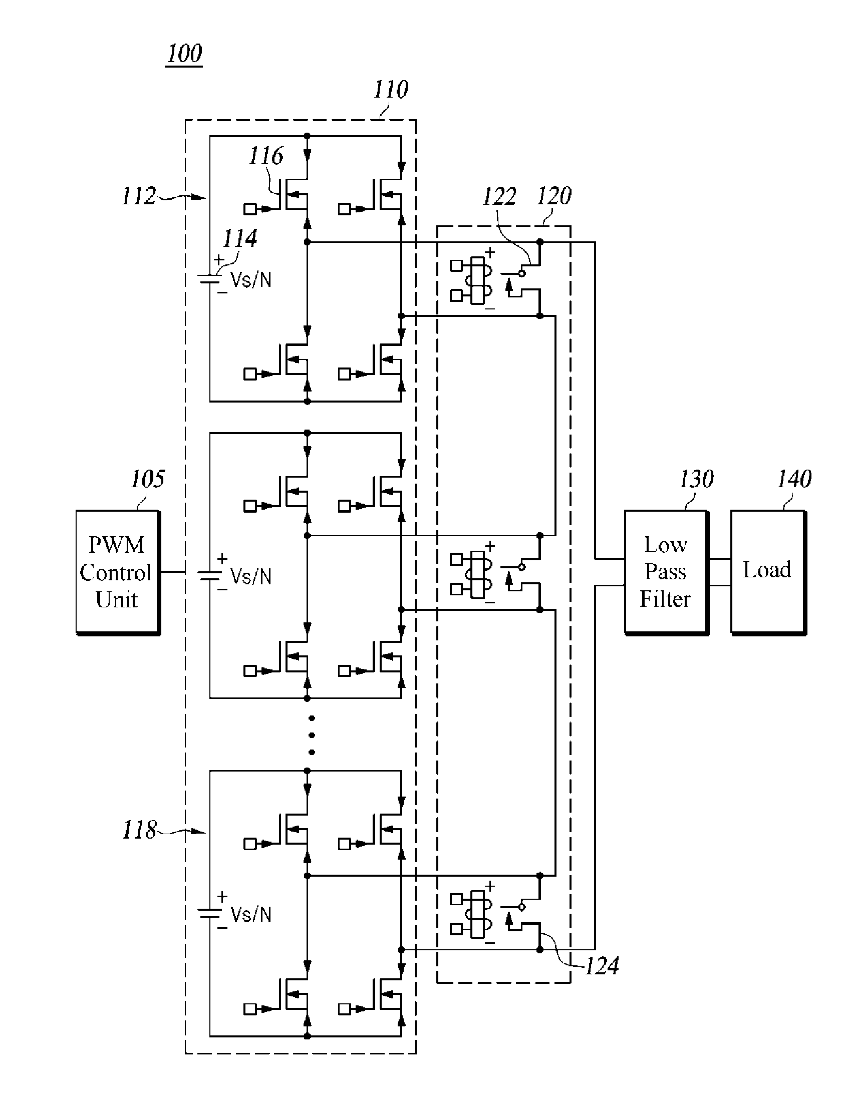
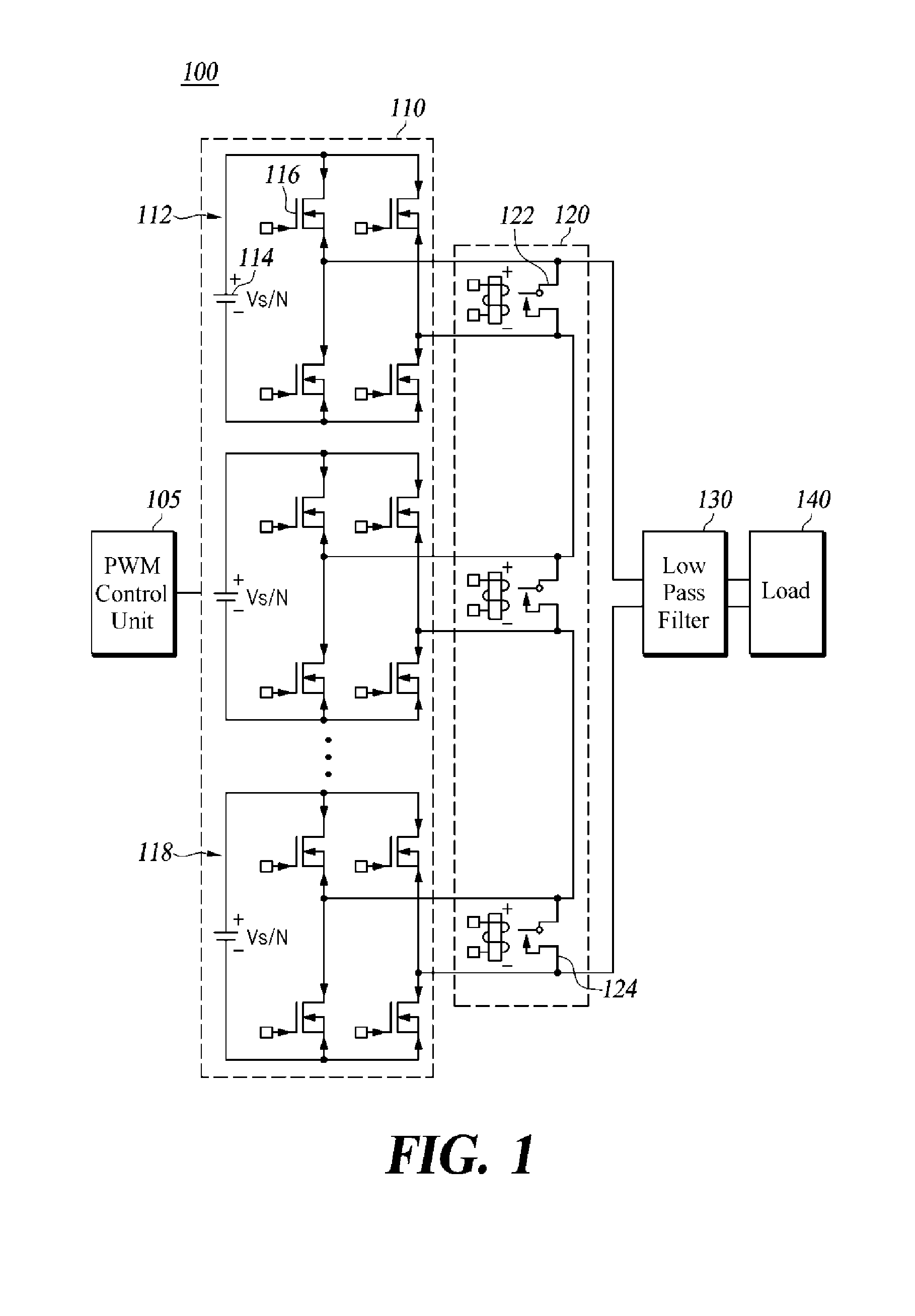
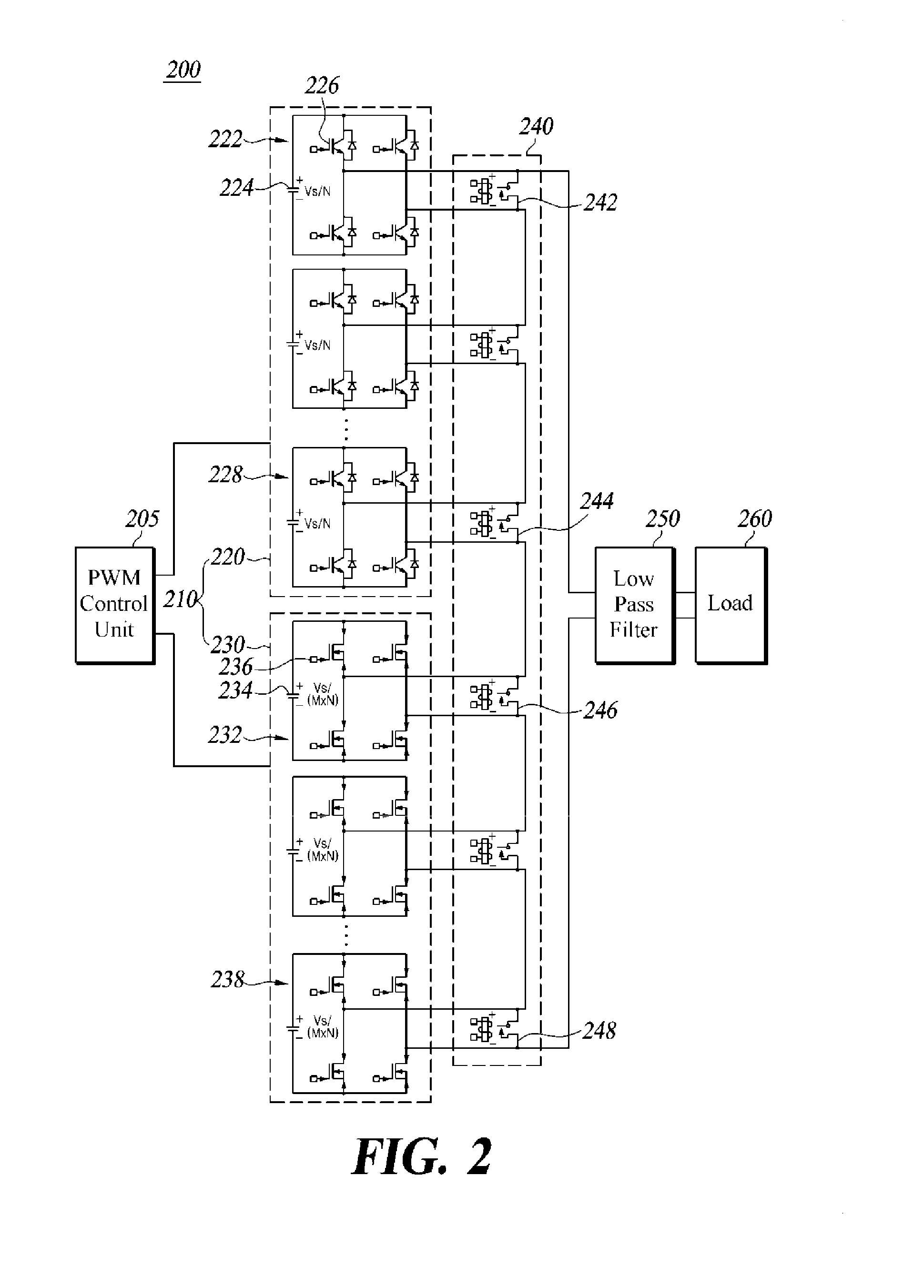
The present disclosure describes a way to increase the reliability and efficiency of a switching amplifier. This is achieved by using a fault-tolerant switching amplifier that has multiple inverters and switches connected in series. This design ensures that if one or more inverters malfunctions, the rest of them are able to keep the amplifier running normally. Additionally, a hybrid switching amplifier that combines the benefits of high withstand voltage and low switching speed is used to minimize conduction and switching loss, resulting in an efficient, low-noise amplified signal.

Problems solved by technology

The linear amplifier has an advantage of broad output bandwidth and low noise; however, there is a disadvantage that, when an output voltage is lower than an input voltage, the efficiency is considerably degraded due to a loss of a semiconductor device.
However, the switching amplifier has a disadvantage that there is a limit in achieving a sufficiently broad bandwidth as it performs the switching with a frequency sufficiently higher than the output bandwidth and that the noise is relatively high as the rectangular wave is generated from a voltage and a current flowing into a switching element according to the switching.
On the other hand, both the linear amplifier and the switching amplifier have a reliability issue that, when they are malfunctional, the input signal cannot be amplified until the amplifiers are recovered from the fault condition.

Method used


Image

  • Switching amplifier and control method therefor
  • Switching amplifier and control method therefor
  • Switching amplifier and control method therefor

Examples


Embodiment Construction

[0020]Hereinafter, at least one embodiment of the present disclosure will be described in detail with reference to the accompanying drawings.

[0021]In the following description, like reference numerals designate like elements although the elements are shown in different drawings. Further, in the following description of the at least one embodiment, a detailed description of known functions and configurations incorporated herein will be omitted for the purpose of clarity and for brevity.

[0022]Additionally, various terms such as first, second, A, B, (a), (b), etc., are used solely for the purpose of differentiating one component from the other but not to imply or suggest the substances, order or sequence of the components. If a component were described as ‘connected’, ‘coupled’, or ‘linked’ to another component, they may mean the components are not only directly ‘connected’, ‘coupled’, or ‘linked’ but also are indirectly ‘connected’, ‘coupled’, or ‘linked’ via one or more additional co...


PUM


Abstract

A fault-tolerant switching amplifier includes an inverter unit including N inverters, where N is a natural number, each of the N inverters including a plurality of switching elements and configured to perform switching ON or OFF of the switching elements based on a PWM signal inputted to the switching elements, thus switching an applied direct-current (DC) voltage, and to generate an output signal based on the switching and a switch unit including N switches respectively connected to output terminals of the N inverters, each of the N switches being configured to be short-circuited or open-circuited based on whether or not the corresponding one of the N inverters is in a normal operation condition. The output terminals of the N inverters are connected in series, such that output signals outputted from the inverters are combined to generate an amplified signal.

Description

TECHNICAL FIELD[0001]The present disclosure relates to a switching amplifier and a control method therefor.BACKGROUND[0002]The statements in this section merely provide background information related to the present disclosure and do not necessarily constitute prior art.[0003]An amplifier is a device that receives a small signal and amplifies it to a large signal. An example of the amplifier that is a common sight in everyday life includes an acoustic amplifier that is called an audio amplifier. Most amplifiers have a scheme of linear amplifier which generates an amplified signal of an input signal by switching on or off a transistor. The linear amplifier has an advantage of broad output bandwidth and low noise; however, there is a disadvantage that, when an output voltage is lower than an input voltage, the efficiency is considerably degraded due to a loss of a semiconductor device.[0004]One of the methods for improving the disadvantage of the linear amplifier is a switching amplifi...

Claims


Application Information

Patent Timeline
Patent Type & Authority Applications(United States)
IPC IPC(8): H03F3/217H03F3/185H03F1/02
CPCH03F3/2171H03F1/0205H03F2200/351H03F2200/03H03F3/185H03F1/523H03F1/526H03F3/217H03F3/2178
Inventor SUNG, HWAN-HO
Owner PS TECH CO LTD
Learn More