Cooler of power converting device for railroad vehicle

a technology of power conversion device and cooling device, which is applied in the direction of chiropractic device, electrical apparatus construction details, physical therapy, etc., can solve the problems of deteriorating cooling performance, inability to perform sufficient radiation, and large loss of igbt and other semiconductor devices, and achieve high safety and reliable detection of temperature

Active Publication Date: 2013-07-25
HITACHI LTD
View PDF2 Cites 8 Cited by
  • Summary
  • Abstract
  • Description
  • Claims
  • Application Information

AI Technical Summary

Benefits of technology

[0034]According to the present invention, it becomes possible to reliably detect the temperature of semiconductor devices having a highest possibility of causing overheat without having to add temperature detecting elements, even when the design maximum speed of the vehicle is incre...

Problems solved by technology

IGBT and other semiconductor devices create a large loss during power conversion, so that a dedicated cooler is required.
The semiconductor devices disposed on the lower area of the power converter are cooled by the outer air having low temperature taken in from the lower area of the cooler, but the semiconductor devices disposed on the upper area of the power converter is cooled using the updraft heated by the lower semiconductor devices, so that sufficient radiation cannot be performed and the cooling performance is deteriorated as a result.
In the case where the cooling performance has been set uniformly in the upper and lower areas (dashed-dotted line of FIG. 9), sufficient traveling wind cannot be acquired when the vehicle is traveling at a slow speed or is at a stop, and in addition, the upper level cooler is influenced by the updraft heated by the cooler on the lower level and the cooling performance thereof is deteriorated significantly, but when the vehicle speed is increased, the cooling performance is improved, which tends to saturate near the design maximum speed.
However, the above-described cooler has the following problems.
It is presumed that such phenomenon is cau...

Method used


Image

  • Cooler of power converting device for railroad vehicle
  • Cooler of power converting device for railroad vehicle
  • Cooler of power converting device for railroad vehicle

Examples


embodiment 1

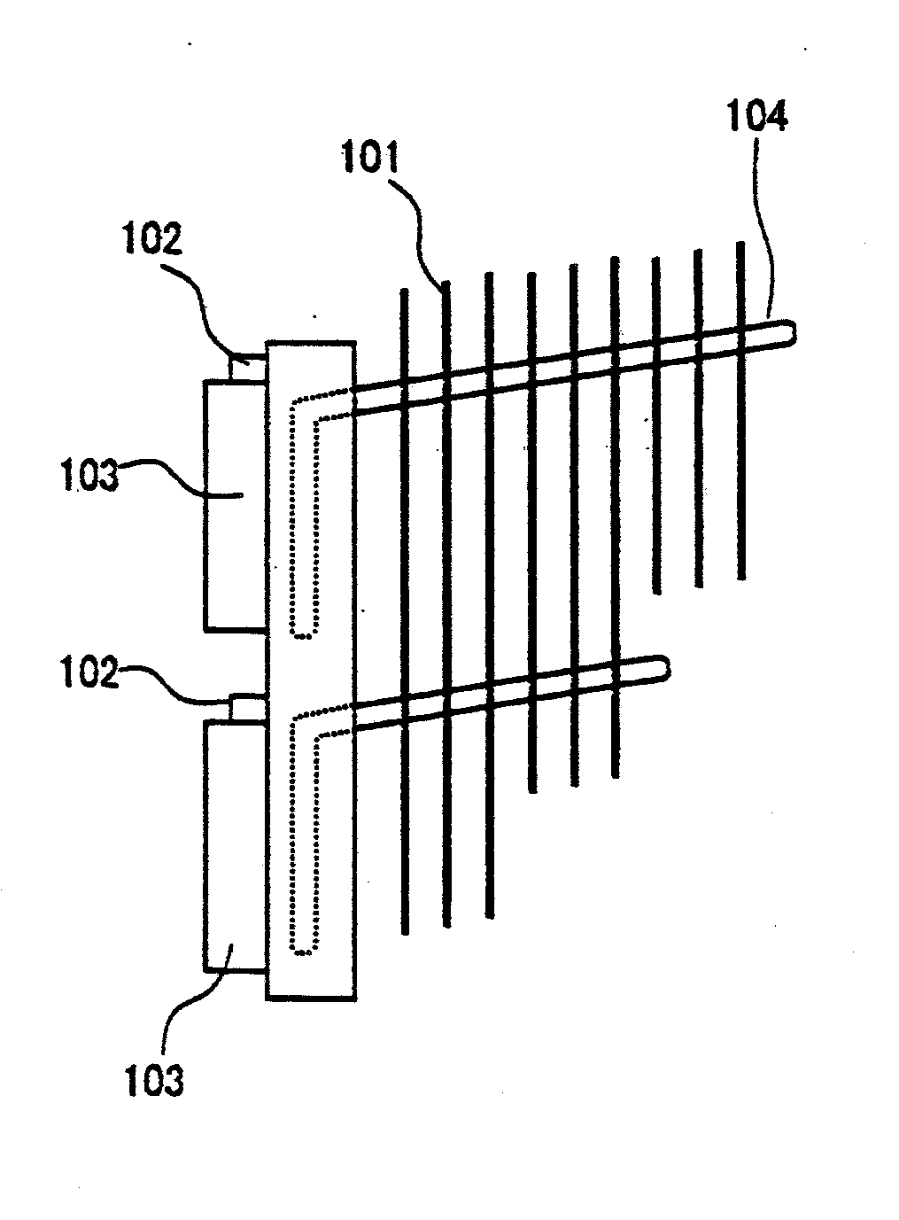
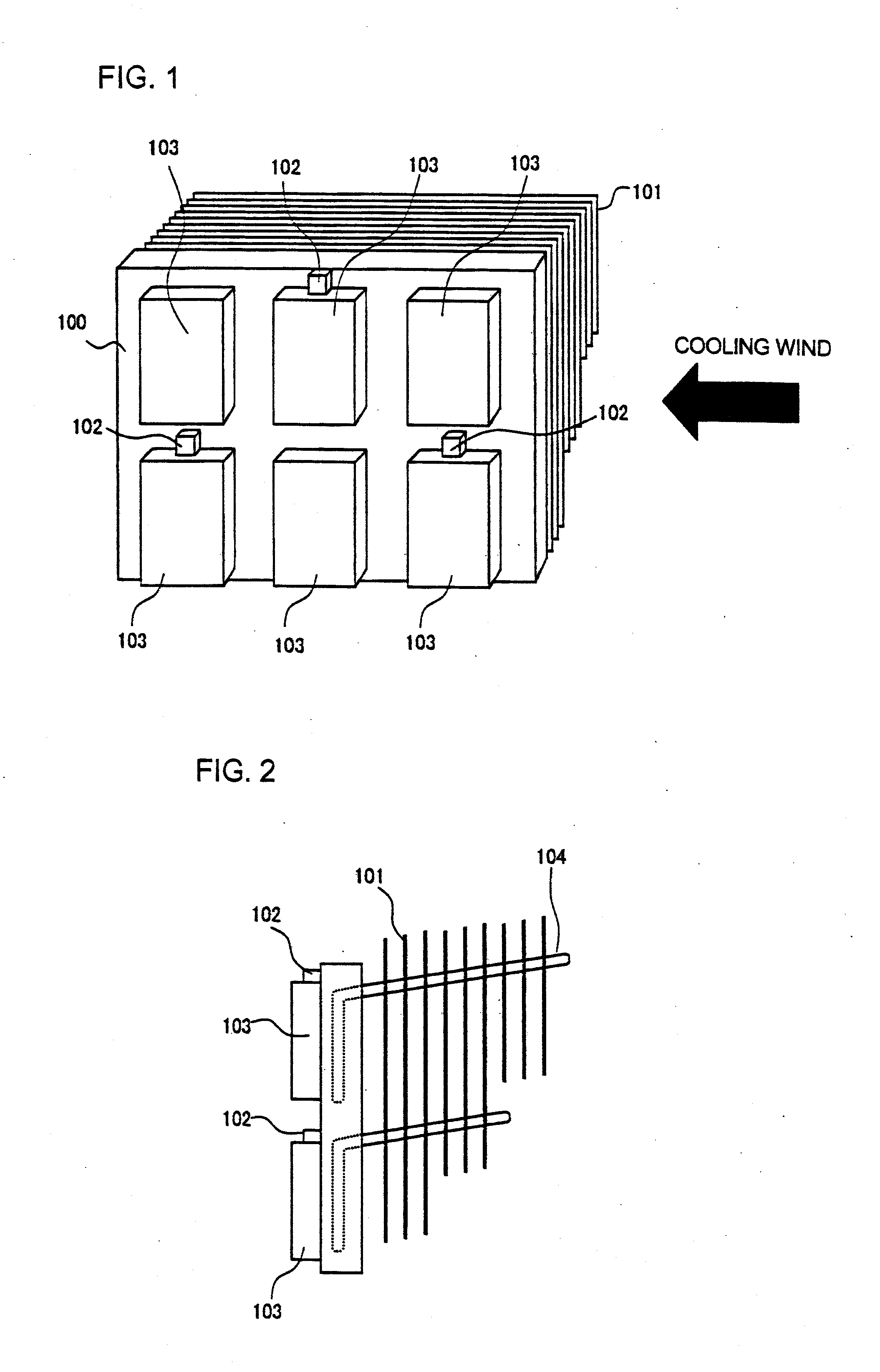
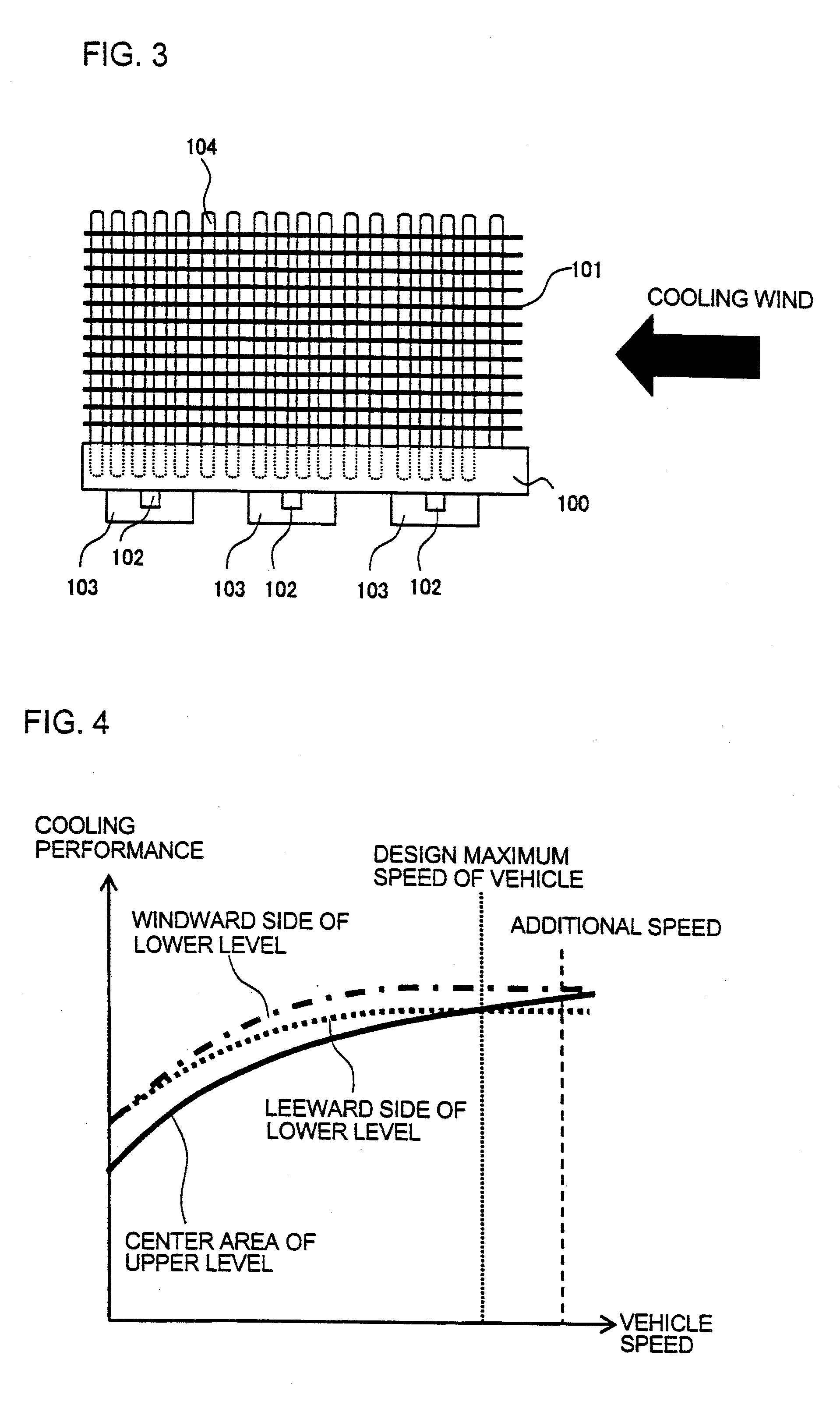
[0045]FIG. 1 is a bird's eye view showing a cooler of a power converting device for a railroad vehicle according to embodiment 1 of the present invention, FIG. 2 is a side view of FIG. 1, and FIG. 3 is an upper view of FIG. 1.

[0046]In FIGS. 1 through 3, 100 denotes a heat absorption panel, 101 denotes heat radiator fins, 102 denotes temperature detecting elements, 103 denotes semiconductor devices, and 104 denotes a heat exchanger tube, adopting a basic configuration similar to the prior art power converting device illustrated in FIGS. 6 through 8 except for the allocation of the temperature detecting element.

[0047]The characteristic feature of the present embodiment is that the temperature detecting elements 102 are arranged on a lower level at a windward side and a leeward side with respect to a cooling wind in the direction of the arrow in FIG. 1, that is, with respect to a traveling wind, and arranged on an upper level at a center area thereof.

[0048]In FIG. 4, the solid line sho...

embodiment 2

[0055]FIG. 5 illustrates the overall configuration of embodiment 2 according to the present invention.

[0056]In FIG. 5, reference number 500 denotes a heat absorption panel, 501 denotes heat radiator fins, 502 denotes temperature detecting elements, and 503 denotes semiconductor devices.

[0057]The characteristic feature of the present embodiment is that when there are three or more levels of semiconductor devices arranged in the vertical direction, the temperature detecting elements 502 are disposed not only at the left and right ends on the lower area but also in the center area.

[0058]The power converter illustrated in FIG. 5 shows an example in which semiconductor devices 503 are arranged in three levels in the vertical direction and five or more rows in the direction of travel of the railroad vehicle.

[0059]According to the illustrated configuration, in a section from where the vehicle travels at low speed to where the vehicle reaches its maximum speed, the center level has four sid...


PUM


Abstract

A cooler of a power converting device for a railroad vehicle has heat exchanger tubes or heat radiator fins disposed to enhance the cooling performance of semiconductor devices arranged on an upper level of the multiple semiconductor devices arranged in multiple rows. Temperature detecting elements are arranged to detect temperature of the semiconductor devices arranged on a lower level on a windward side and a leeward side with respect to a traveling wind performing heat exchange with the heat radiator fins, and are arranged to detect temperature of the semiconductor devices arranged on the upper level at a center area thereof.

Description

[0001]The present application is based on and claims priority of Japanese patent application No. 2012-009734 filed on Jan. 20, 2012, the entire contents of which are hereby incorporated by reference.BACKGROUND OF THE INVENTION[0002]1. Field of the Invention[0003]The present invention relates to a power converting device mounted on a railroad vehicle, and especially relates to a cooler for semiconductor devices disposed on the power converting device.[0004]2. Description of the Related Art[0005]A railroad vehicle is designed to travel by converting commercial-frequency AC power or a DC power to a three-phase AC having variable frequency and driving a motor thereby. As a power converter for converting power, a variable voltage variable frequency (VVVF) inverter or the like that uses multiple semiconductor devices such as IGBTs as power semiconductor switching elements and converting DC into three-phase AC having variable frequency is widely used.[0006]IGBT and other semiconductor devi...

Claims


Application Information

Patent Timeline
IPC IPC(8): H05K7/20
CPCH05K7/20336H05K7/2089H05K7/20936H01L2924/0002H01L2924/00A61F5/0111A61F5/0127A61H1/02A61H1/0266A61F2005/0167
Inventor KONISHIDE, MASAOMIKONO, YASUHIKOHISHIDA, AKIHIRO
Owner HITACHI LTD
Why Eureka
Try Eureka