Temperature measuring apparatus and temperature measuring method

a technology of temperature measurement and measuring apparatus, which is applied in the direction of instruments, heat measurement, material analysis, etc., can solve the problems of difficult temperature detection, difficult to identify exactly which measurement point the interference waveform originates, etc., and achieves more accurate and efficient processing in the substrate. , the effect of reliably detecting the temperature of the poin

Active Publication Date: 2008-09-11
TOKYO ELECTRON LTD
View PDF7 Cites 3 Cited by
  • Summary
  • Abstract
  • Description
  • Claims
  • Application Information

AI Technical Summary

Benefits of technology

[0015]In accordance with the present invention, it is possible to provide a temperature measurement apparatus and method capable of identifying an interference waveform from each measurement point to reliably detect a temperature of the point even when the number of measurement points is large, thereby making it possible to perform a more accurate and efficient processing in a substrate and the like.

Problems solved by technology

However, the above prior art has a drawback in that, if the number of measurement points is further increased, it becomes difficult to identify exactly which of the measurement points an interference waveform originates from.
This makes the temperature detection more difficult, or may cause a misdetection.

Method used


Image

  • Temperature measuring apparatus and temperature measuring method
  • Temperature measuring apparatus and temperature measuring method
  • Temperature measuring apparatus and temperature measuring method

Examples


second embodiment

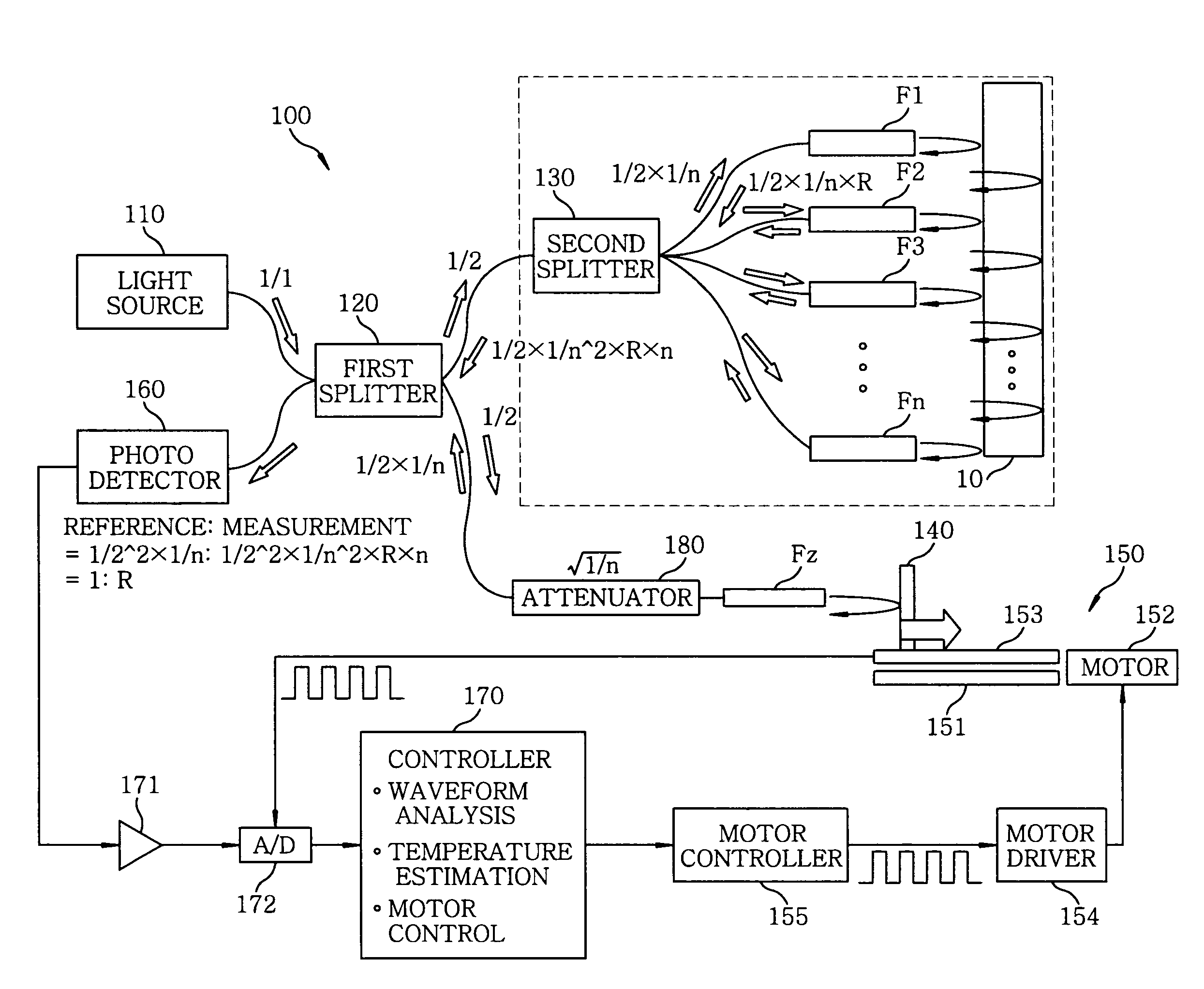
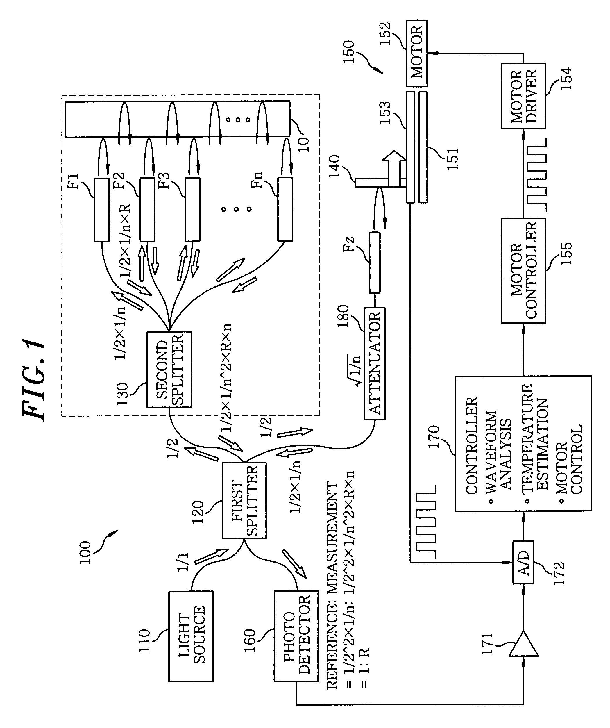
[0053]Hereinafter, the present invention will be described with reference to FIG. 3. A temperature measurement apparatus 200 shown in FIG. 3 employs a single splitter 220 for splitting a light beam emanated from the light source 110, instead of the first splitter 120 and the second splitter 130 in FIG. 1. The splitter 220 splits the light beam generated from the light source 110 into (N+1) number of beams including a first to an nth measuring beam and a reference beam. The other parts are the same as those of the temperature measurement apparatus 100 shown in FIG. 1.

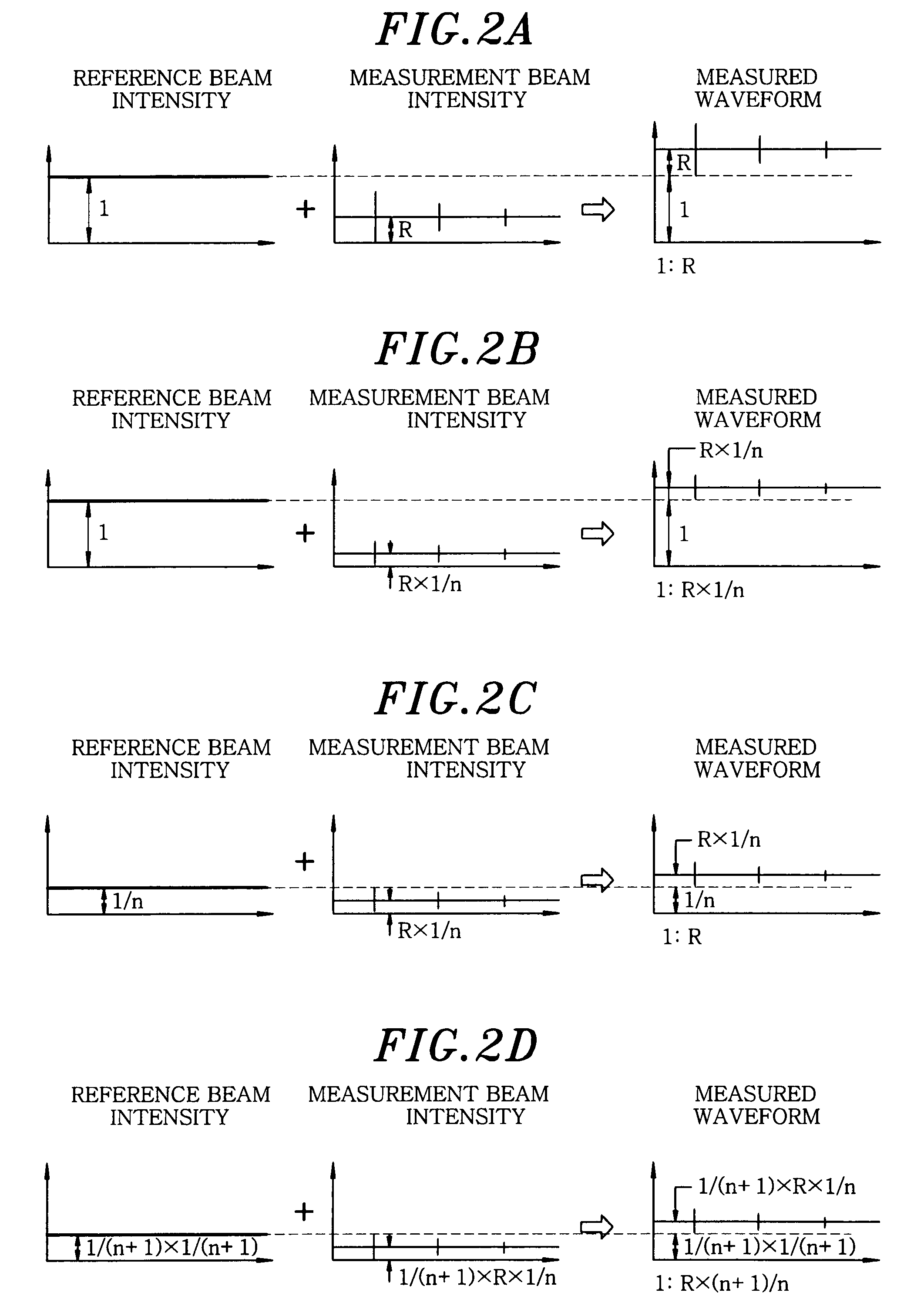
[0054]As shown in FIG. 2D, in case of employing the temperature measurement apparatus 200, the ratio of the intensity of the reference beam to that of the measurement beam included in a measured waveform is 1:R×(n+1) / n (i.e., reference beam:measurement beam=1:R×(n+1) / n), which is approximately the same as in case of the one-point measurement. In this manner, it is possible to improve the S / N ratio in comparison with the ...

third embodiment

[0055]Next, the present invention will be described with reference to FIG. 4. As shown therein, a temperature measurement apparatus 300 does not include the attenuator 180 in the temperature measurement apparatus 100 of FIG. 1, but instead includes an AC component extractor 310 capable of extracting an AC component from a detection signal of the photodetector 160. In addition, the temperature measurement apparatus 300 further includes a switch 311 for switching the state of the AC component extractor 310 between a first state where the AC component is extracted by the AC component extractor 310 and a second state where the total signal passes through the AC component extractor 310, thereby making it possible to check the DC level (light intensity). The other parts of the temperature measurement apparatus 300 are the same as those of the temperature measurement apparatus 100 shown in FIG. 1.

[0056]In accordance with the temperature measurement apparatus 300, the AC component can be ex...


PUM

PropertyMeasurementUnit
center wavelengthaaaaaaaaaa
coherence lengthaaaaaaaaaa
thicknessaaaaaaaaaa

Abstract

A temperature measuring apparatus includes a light source, a first splitter, a second splitter, a reference beam reflector, an optical path length adjuster, a reference beam transmitting member, a first to an nth measuring beam transmitting member and a photodetector. The temperature measuring apparatus further includes a controller that stores, as initial peak position data, positions of interference peaks respectively measured in advance by irradiating the first to the nth measuring beam onto the first to the nth measurement point of the temperature measurement object, and compares the initial peak position data to positions of interference peaks respectively measured during a temperature measurement to thereby estimate a temperature at each of the first to the nth measurement point.

Description

FIELD OF THE INVENTION[0001]The present invention relates to a temperature measuring apparatus and a temperature measuring method capable of accurately measuring a temperature of, e.g., an a front surface, a rear surface and an inner layer of an object such as a semiconductor wafer, a liquid crystal display substrate and the like.BACKGROUND OF THE INVENTION[0002]In general, accurate measurement of a temperature of a substrate (e.g., a semiconductor wafer) to be processed by a substrate processing apparatus is very important in controlling the shape and property of a film, a hole and the like formed thereon by various processes such as film forming, etching and the like. For this reason, various methods of measuring a temperature of a semiconductor wafer, including a measurement method using a resistance thermometer or a fluorescent thermometer for measuring a temperature of a rear surface of a substrate and the like, have been performed.[0003]In recent years, a temperature measureme...

Claims


Application Information

Patent Timeline
Patent Type & Authority Applications(United States)
IPC IPC(8): G01N21/00
CPCG01K11/125
Inventor ABE, JUNMATSUDO, TATSUOKOSHIMIZU, CHISHIO
Owner TOKYO ELECTRON LTD
Why Eureka
Try Eureka