Mobile communication system, mobility management apparatus, data delivering apparatus, mobile communication method, and program

a mobile communication system and mobile communication technology, applied in the field of mobile communication system, can solve the problems of inability to determine in advance, limited distribution range, etc., and achieve the effects of suppressing signaling traffic to a low level, improving reception quality, and improving network resources and radio resources

Inactive Publication Date: 2013-07-25
SHARP KK
View PDF5 Cites 23 Cited by
  • Summary
  • Abstract
  • Description
  • Claims
  • Application Information

AI Technical Summary

Benefits of technology

[0055]Thus, the mobility management apparatus does not select the destination cell of conventional multicast data, but sets up multicast delivery paths to all the base station apparatuses the mobility management apparatus manages in the mobile communication system. However, in the present invention, the mobility management apparatus dynamically selects the delivery designation base station apparatuses depending on the cell in which a mobile station apparatus exists as well as the surrounding cells of the cell in which the mobile station apparatus exists, hence the selected base station apparatuses alone participate in the delivery paths so that it is not necessary to set up waste delivery paths, thus improving efficiency of network resources and radio resources.
[0056]Similarly, conventionally it was necessary to transmit a session start request to all the base station apparatuses which the mobility management apparatus manages in the mobile communication system. However, according to the present invention, it is not necessary to distribute the session start request message to all the base station apparatuses, it is hence possible to suppress signaling traffic to a low level.
[0057]Upon selection of base station apparatuses, by selecting base station apparatuses for the surrounding cells (e.g., adjacent cells) inclusive of the cell in which the mobile station exists despite the fact that the cell in which the mobile station apparatus is a single cell, it is possible to make full use of the function of MBMS multi-cell transmission mode (the function of a mobile station apparatus located at the edge of cell to improve the quality of reception by synthesizing data received from a plurality of base station apparatuses) and it is also possible to easily deal with movement of the mobile station apparatus to a surrounding cell. Further, since it is possible to widen the selection range of surrounding cells or limit the selection range within only the cell in which the mobile station apparatus exists, depending on the mobile capability of the mobile station apparatus, it is possible to determine the delivery destination area in an efficient and flexible manner.
[0058]Further, the conventional information notified from a mobile station apparatus in the attach or location register phase and in the multicast group join phase may be used as the information on the mobile station apparatus which the multicast service delivering apparatus and the mobility management apparatus of the present invention manage, it is hence possible to offer multicast services without adding extra processing loads for notifying new information to the mobile station apparatus and other reasons.

Problems solved by technology

Differing from the prior art, data distribution in services of this kind is characterized in that the range of distribution is limited depending on the service to be offered and the related terminals are unevenly distributed geographically.
Further, the place and time of the offered service is dynamically configured and hence cannot be determined in advance.

Method used


Image

  • Mobile communication system, mobility management apparatus, data delivering apparatus, mobile communication method, and program
  • Mobile communication system, mobility management apparatus, data delivering apparatus, mobile communication method, and program
  • Mobile communication system, mobility management apparatus, data delivering apparatus, mobile communication method, and program

Examples


first embodiment

1. The First Embodiment

[0078]To begin with, the first embodiment will be described.

[0079][1.1 System Configuration]

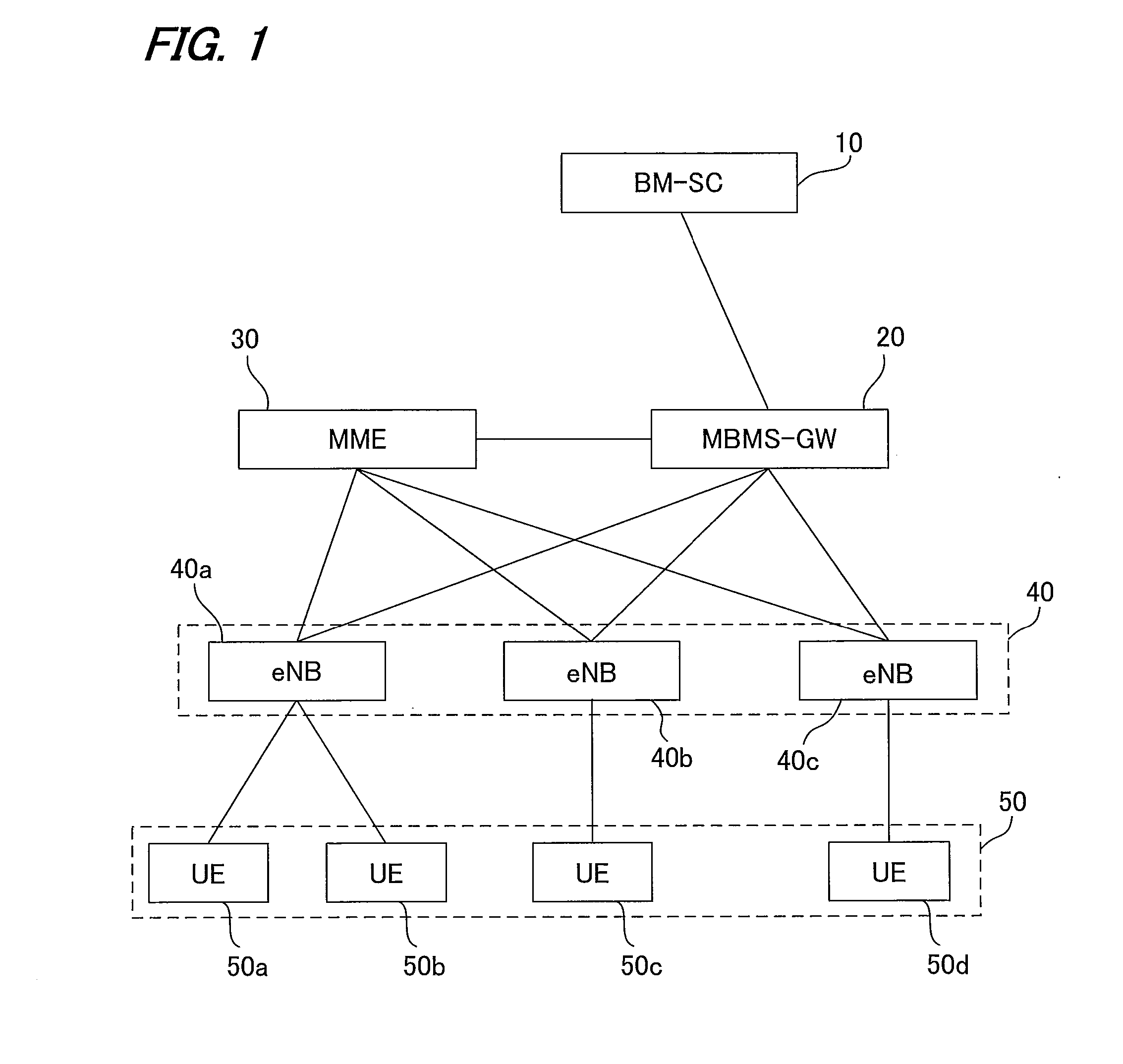
[0080]FIG. 1 is a diagram for illustrating a system configuration of a mobile communication system 1 to which the present invention in the first embodiment is applied, including a BM-SC 10 (Broadcast-Multicast Service Center), an MBMS-GW 20, a core network including an MME (Mobile Management Entity) 30, a radio access network including eNBs (Evolved Node B) 40 (eNB 40a, eNB 40b, eNB 40c) and UEs (User Equipment) 50 (UE 50a, UE 50b, UE 50c, UE 50d).

[0081]BM-SC 10 is an apparatus (multicast service delivering apparatus) for controlling distribution of multicast services, and is connected to MBMS-GW 20 as an edge node in the core network. MBMS-GW 20 is connected to eNBs 40 and MME 30 that performs control relating multicast bearer setup and the like of eNBs 40. MME 30 is also connected to eNBs 40.

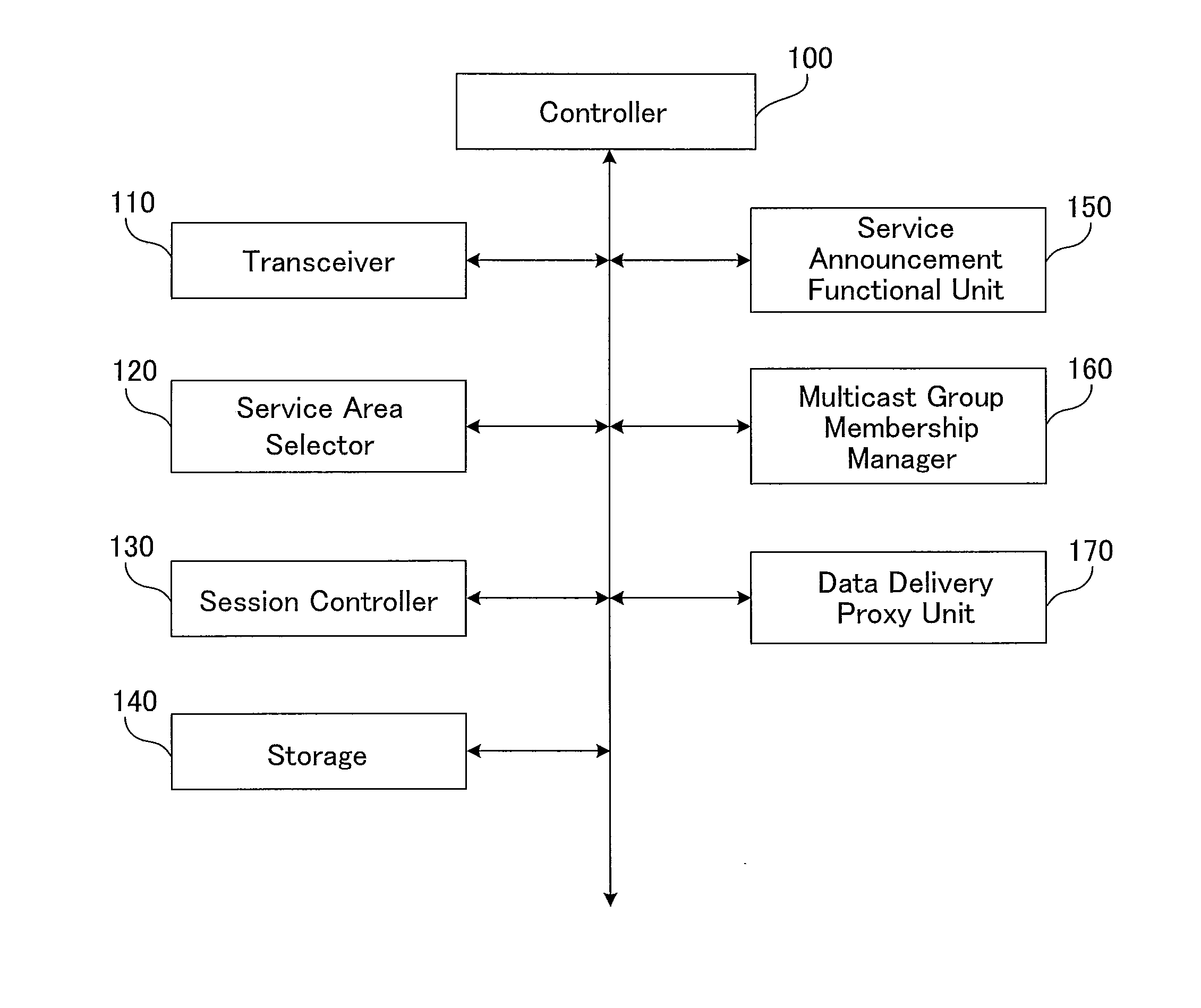
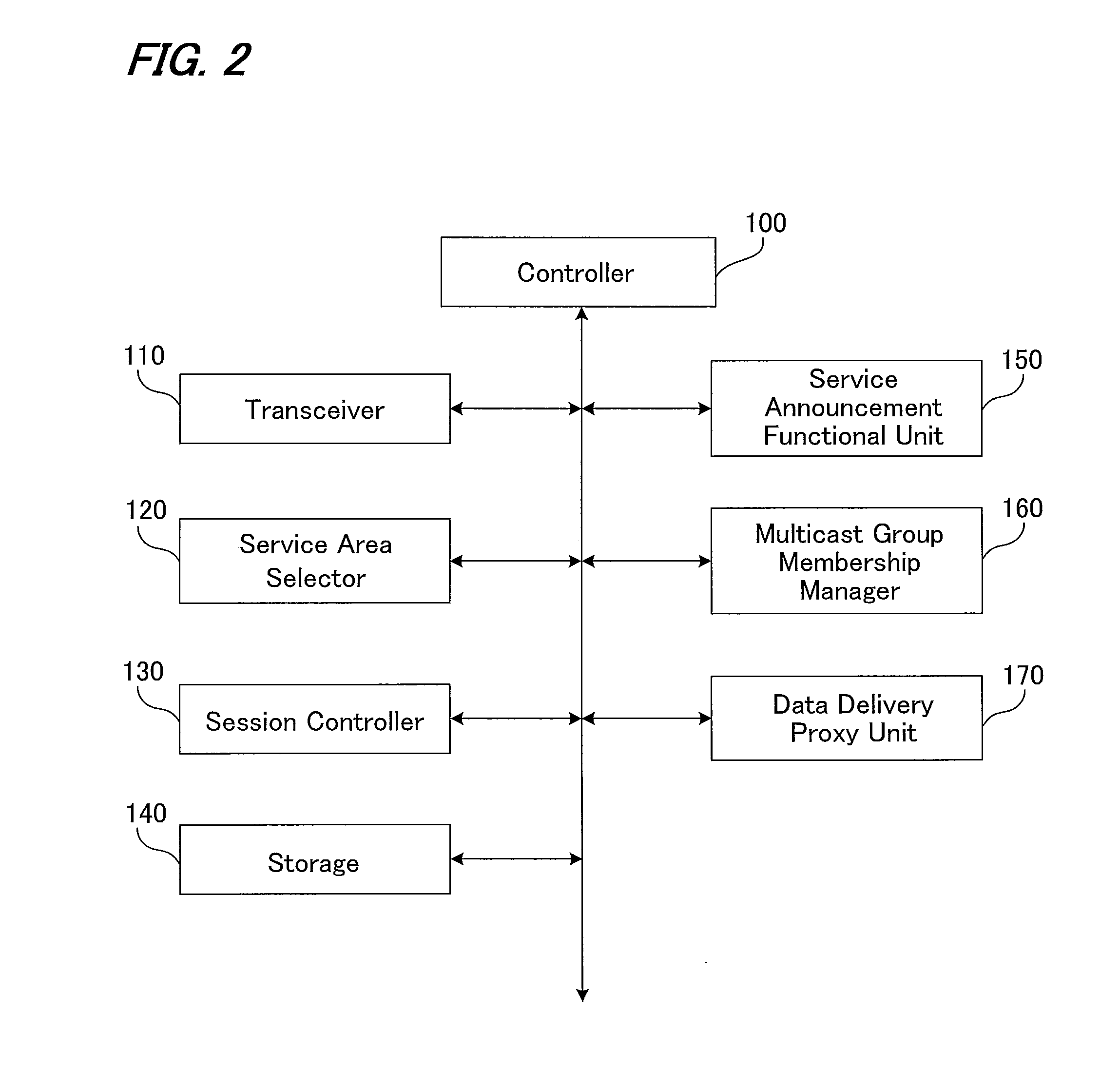
[0082]Here, MME 30 is a mobility management apparatus for managing mobile sta...

second embodiment

2. The Second Embodiment

[0194]Next, the second embodiment will be described.

[0195][2.1 System Configuration]

[0196]FIG. 11 is a diagram illustrating a system configuration of the second embodiment of the present invention. In the configuration of the present embodiment, eNB 40 (eNB 40a, eNB 40b, eNB 40c) includes a MCE (Multi-cell / multicast Coordination Entity) 35 (MCE 35a, MCE 35b, MCE 35c) as a functional unit for coordinating radio resources between a plurality of eNBs when performing multicast. This MCE 35 enables eNBs 40 to set up a multicast bearer using the same radio resources in each cell.

[0197]In this configuration, MME 30 is connected to eNBs 40, but the entity to be controlled on radio resource setup is MCE 35 in eNB 40. Accordingly, the interface to be used is different from that in the first embodiment. Specifically, S1-MME interface defined in EPS is used between MME 30 and eNB 40, whereas M3 interface is used between MME 30 and MCE 35. Since other nodes are the same a...

third embodiment

3. The Third Embodiment

[0208]Next, the third embodiment will be described.

[0209][3.1 System Configuration]

[0210]FIG. 14 is a diagram for illustrating the system configuration of the third embodiment of the present invention. In the configuration of the present embodiment, MCE 35 is configured independently from eNBs 40 (eNB 40a, eNB 40b, eNB 40c) of the second embodiment. This configuration enables MCE 35 to function as a superior node of eNBs 40 and perform efficient coordination of radio resources.

[0211]In this case, specifically the interface between MCE 35 and eNB 40 is called M2 interface. MCE 35 functions as the direct controller of eNBs 40 with respect to radio resource setup, similarly to the second embodiment. However, MCE 35 and eNB 40 are related in a one-to-one correspondence manner in the second embodiment, whereas MCE 35 and eNBs 40 are associated in a one-to-many correspondence manner in the present embodiment. Accordingly, MME 30 does not need to individually transmi...


PUM


Abstract

In a mobile communication system, a service area is constituted of a plurality of cells each disposing a base station, and offers a multicast service to a mobile station apparatus in the service area, by transmitting multicast data to the base stations in the service area when a session initiation request includes a dynamic service area constitution identifier. A cell disposed a base station apparatus in which the mobile station apparatus exists as well as cells surrounding the concerned cell is determined as a dynamic service area and a session start request is transmitted to the base stations included in the service area. As a result, multicast data will be delivered to the base stations around which a mobile terminal exists, thus providing a mobile communication system which can perform efficient communication without using waste resources.

Description

TECHNICAL FIELD[0001]The present invention relates to a mobile communication system and the like.BACKGROUND ART[0002]In 3GPP, as a method of offering multicast services based on the EPS (Evolved Packet System), standardization of MBMS (Multimedia Broadcast / Multicast Service) has been in progress.[0003]According to non-patent document 1, for example, an MBMS service area is defined as a range in which MBMS sessions are conducted. For example, the service area is set up in a regional unit such as the whole of Japan, the Kanto area, and the like, and the service area is constituted of a plurality of cells therein. Then, delivery paths of multicast data (which will be called multicast delivery paths hereinbelow) are configured in the interior of the EPC (Evolved Packet Core) that constitutes the EPS and the interior of a radio access network such as E-UTRAN, UTRAN or the like that is connected to the EPC. The base station (eNodeB in E-UTRAN) of each cell in the service area or the radio...

Claims


Application Information

Patent Timeline
Patent Type & Authority Applications(United States)
IPC IPC(8): H04W72/00
CPCH04W4/06H04W72/005H04W76/02H04W28/06H04W76/10H04W72/30
Inventor MORIWAKI, TETSUROARAMOTO, MASAFUMINAOE, HIROKAZU
Owner SHARP KK
Why Eureka
Try Eureka