Mechanical positioning system for surgical instruments

a positioning system and surgical instrument technology, applied in the field of external manipulators, can solve the problems of voluminous current surgical robots, non-ergonomic, non-intuitive, and inability to provide adequate visual and tactile feedback, and achieve the effect of sufficient dexterity and precision

Inactive Publication Date: 2013-07-25
ECOLE POLYTECHNIQUE FEDERALE DE LAUSANNE (EPFL)
View PDF1 Cites 8 Cited by
  • Summary
  • Abstract
  • Description
  • Claims
  • Application Information

AI Technical Summary

Benefits of technology

[0025]More specifically, an aim of the present invention is to provide a novel external positioning manipulator able to provide sufficient dexterity and precision to position the MIS instruments. The unique design of the proposed system permits to keep the above mentioned characteristics at any location within the abdominal cavity. Extensive discussions with the surgical community have provided a precious input to establish a highly innovative engineering surgical system.

Problems solved by technology

However, from the surgeon's point of view there are still many difficulties in learning and performing such procedures with current laparoscopic equipment, which is non-ergonomic, non-intuitive and missing in adequate visual and tactile feedback.
One of the major open drawbacks is that the current surgical robots are voluminous, competing for precious space within the operating room (OR) environment and significantly increasing ORs preparation time.
Access to the patient is thus impaired and this raises safety concerns.
In addition, although robotic systems offer excellent vision and precise tissue manipulation within a defined area, they are limited in operations involving more than one quadrant of the abdomen.
Another drawback of current surgical systems is related to the mechanisms that hold and place the surgical instruments into the abdomen, remaining external to the patient.
Their access within the abdomen is limited since the instruments are constrained by the abdominal wall at their point of entry.
They are also further restricted by this fulcrum effect, due to the fact that their internal motion is mirrored and magnified outside the body by the robotic arms.
Moreover, surgical instruments have limited space to move, leading to eventual collisions.
This may result in: (1) addition of inertial loads that adversely affect system performance or (2) lack of DOEs to place and guide the MIS instruments within the abdominal cavity.
This may result in: (1) addition of inertial loads that adversely affect system performance [Berkelman2003], [Berkelman2006] or (2) lack of DOEs to place and guide the MIS instruments within the abdominal cavity [Lum2004], [Lum2006].

Method used


Image

  • Mechanical positioning system for surgical instruments
  • Mechanical positioning system for surgical instruments
  • Mechanical positioning system for surgical instruments

Examples


Embodiment Construction

[0054]The present invention will be better understood by a detailed description of several embodiments therefrom and by reference to the following drawings in which

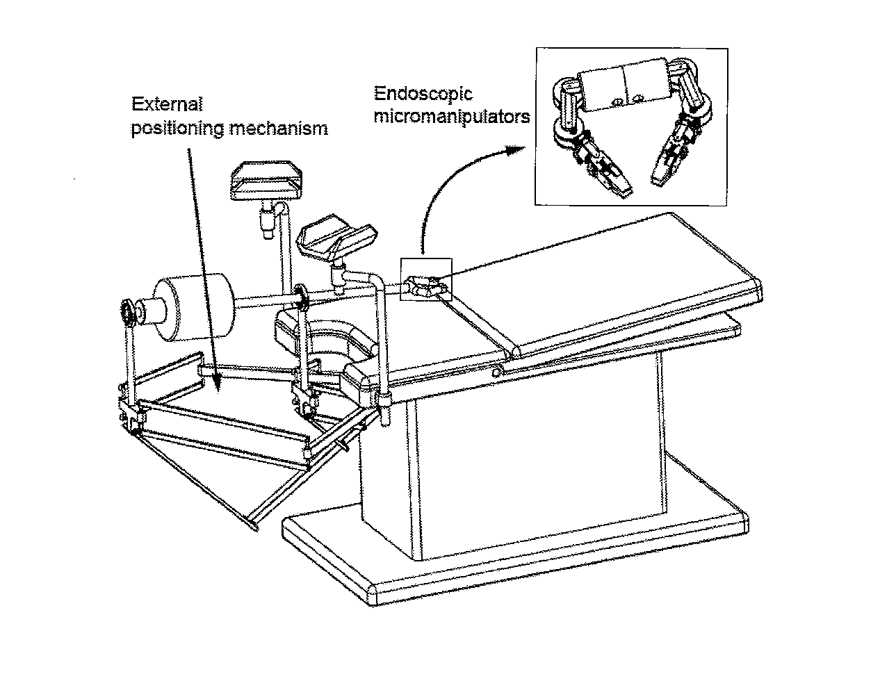
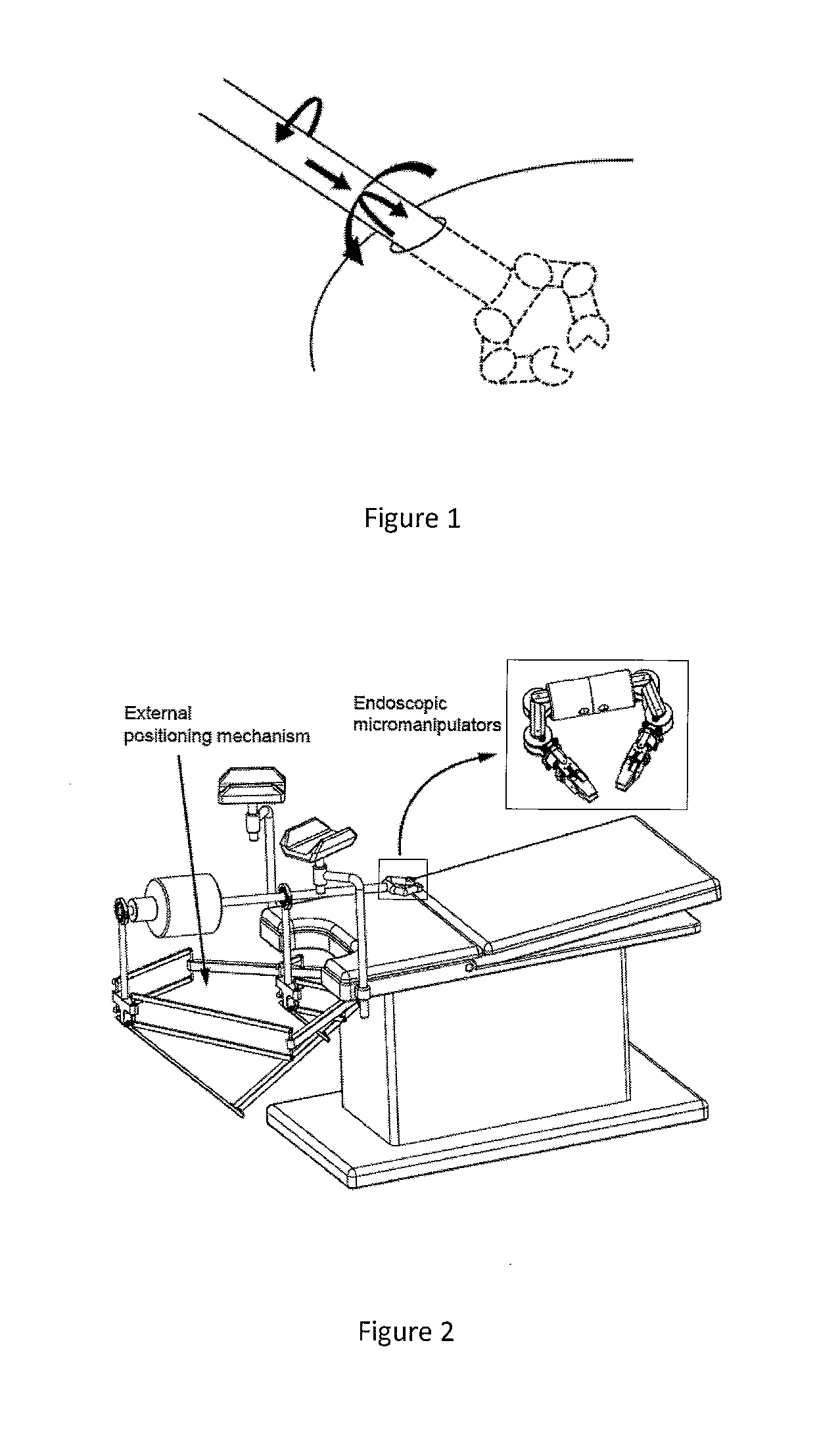
[0055]FIG. 1 illustrates a conceptual representation of a surgical platform;

[0056]FIG. 2 illustrates a conceptual design of the complete surgical platform;

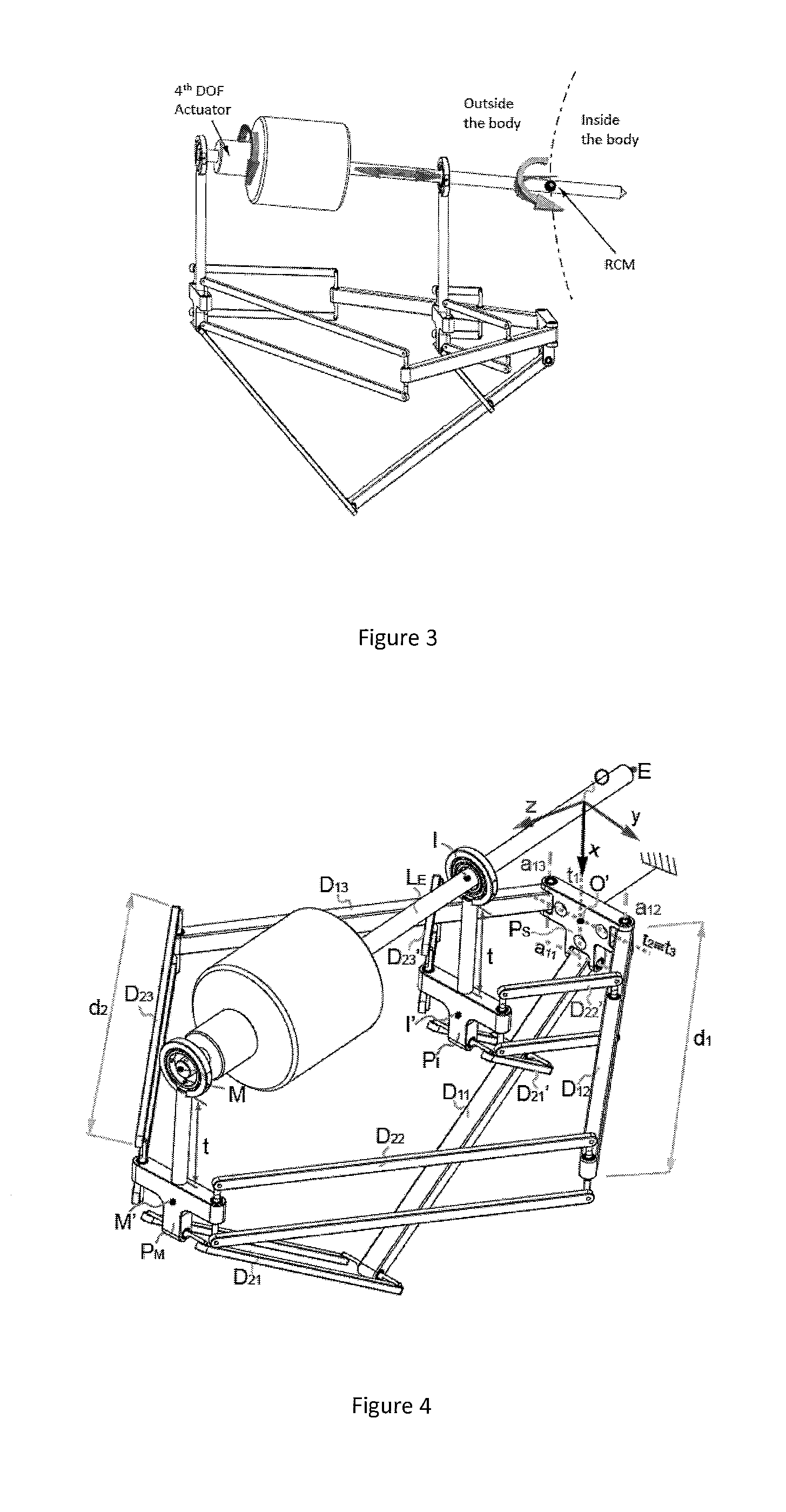
[0057]FIG. 3 illustrates degrees of freedom of an external manipulator;

[0058]FIG. 4 illustrates external manipulator schematics;

[0059]FIG. 5 illustrates limb schematics;

[0060]FIG. 6 illustrates the Intercept Theorem;

[0061]FIG. 7 illustrates a 2D representation of manipulator kinematics;

[0062]FIG. 8 illustrates examples of potential working configurations for the external manipulator;

[0063]FIG. 9 illustrates a kinematic structure of the external manipulator

[0064]FIG. 10 illustrates examples of singular configurations;

[0065]FIG. 11 illustrates profiles generating the nth limb workspace;

[0066]FIG. 12 illustrates workspace surfaces for each limb;

[0067]FIG. 13 illustrates a ...


PUM


Abstract

An external manipulator for positioning surgical instruments within the abdominal cavity, comprising a hybrid kinematics with a parallel structure, able to provide four, active or passive, positional degrees of freedom to a endoscopic unit, placed in the distal end of an instrument shaft. Due to this specific kinematics, the instrument shaft is able to perform two rotations, one translation, and a fourth orientation degree of freedom about a remote centre of rotation, coincident with the surgical incision port. Because of its unique design and kinematics, the proposed mechanism is highly compact, stiff and its dexterity fulfils the workspace specifications for surgical procedures.

Description

FIELD OF THE INVENTION[0001]The present invention concerns an external manipulator for positioning surgical instruments within the abdominal cavity. More specifically, the manipulator comprises a hybrid kinematics with a parallel structure, able to provide four, active or passive, positional degrees of freedom to a endoscopic unit, placed in the distal end of an instrument shaft.BACKGROUND OF THE INVENTION[0002]A major progress in abdominal surgery has occurred during the last decades with the introduction of laparoscopic and minimally invasive techniques. These innovative procedures focused much attention due to their several advantages: smaller abdominal incisions needed, resulting in faster recovery of the patient, improved cosmetics, and shorter stay in the hospital. The safety, efficiency and cost-effectiveness of laparoscopic surgery have subsequently been demonstrated in clinical trials for many routine abdominal operations. However, from the surgeon's point of view there are...

Claims


Application Information

Patent Timeline
Patent Type & Authority Applications(United States)
IPC IPC(8): A61B19/00
CPCA61B19/2203A61B2019/2215A61B19/22A61B2019/265A61B2019/2249A61B2034/302A61B2090/506A61B34/70A61B34/30A61B34/72
Inventor BEIRA, RICARDOREYMOND, CLAVELBLEULER, HANNES
Owner ECOLE POLYTECHNIQUE FEDERALE DE LAUSANNE (EPFL)
Why Eureka
Try Eureka