
System and method for operation of an HVAC system to adjust ambient air temperature

Inactive Publication Date: 2013-07-25
RES PRODS
View PDF5 Cites 36 Cited by
  • Summary
  • Abstract
  • Description
  • Claims
  • Application Information

AI Technical Summary

Benefits of technology

The present invention is an HVAC control system that lets users adjust the temperature of their environment for temporary comfort. The system allows for manual activation and will return to the original programming when the desired temperature is reached. This means users don't need to readjust or program the system once they've achieved the desired cooling or heating. The control system can also activate a timer to automatically return to the original programming when the desired temperature is reached. The invention includes a method for adjusting the temperature of a space using the HVAC system.

Problems solved by technology

However, known thermostats and related programmable controls for an HVAC control system have certain limitations.
For example, in instances where a user desires to temporarily adjust the ambient temperature of an environment to improve the short term comfort of the user, the user generally has a limited number of system control options.
In addition, a permanent temporary hold of a manually adjusted temperature set point can result in unwanted additional expense, as the HVAC system will continue to operate until the permanent hold is removed.
In addition, a prolonged “temporary hold” of the manually adjusted temperature set point can result in unwanted additional expense, as the HVAC system would continue to operate even after the user has attained the desired short term comfort and / or the user leaves the environment controlled by the HVAC system.
As a fourth option, many users and / or homeowners have difficulty adjusting programmable thermostats more complex than a manual adjustment of a current temperature setting.
The users and / or homeowners may then endure less than optimal temperatures and / or undesirable short term comfort until the next program change.

Method used


Image

  • System and method for operation of an HVAC system to adjust ambient air temperature
  • System and method for operation of an HVAC system to adjust ambient air temperature
  • System and method for operation of an HVAC system to adjust ambient air temperature

Examples


Embodiment Construction

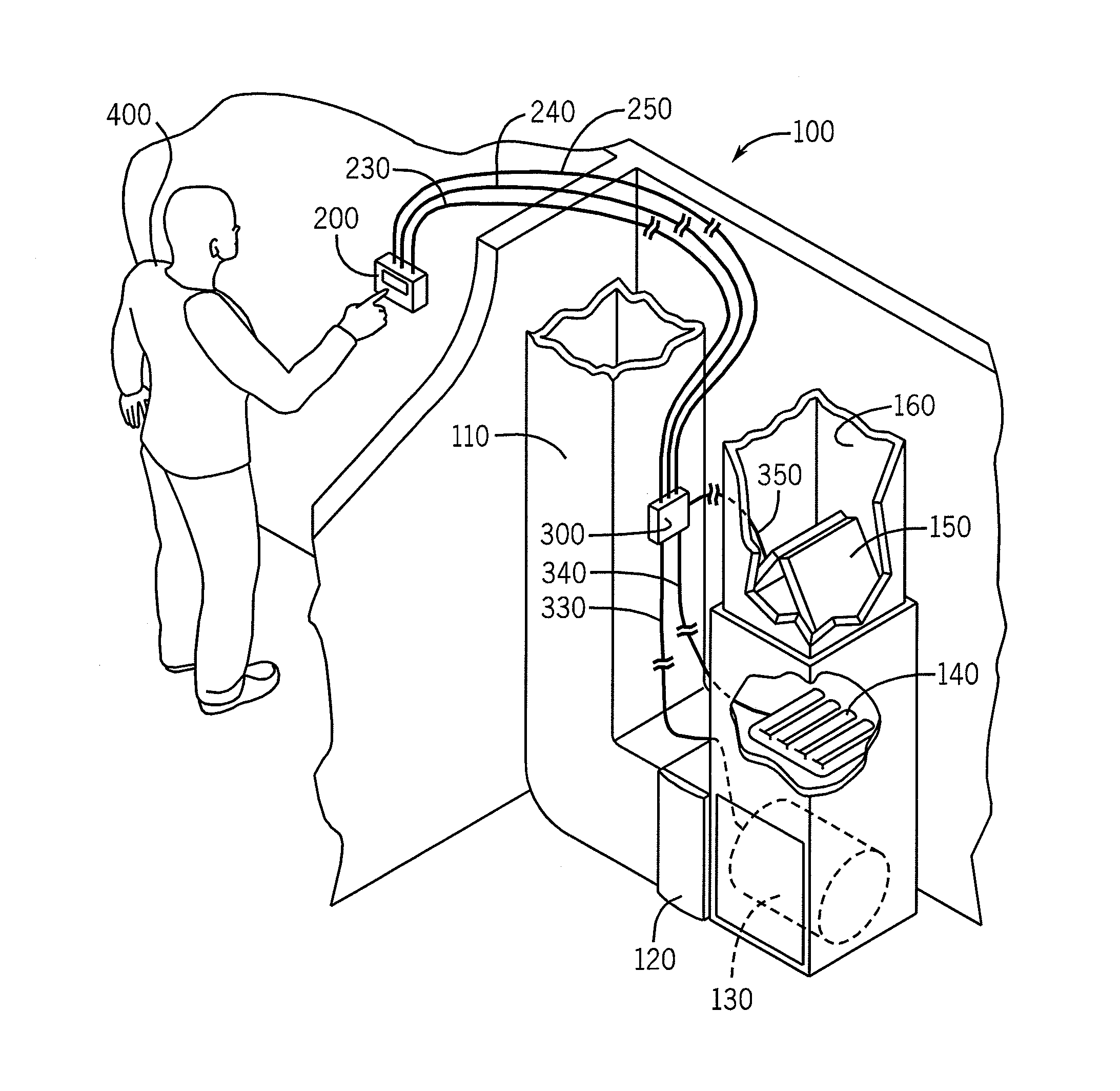
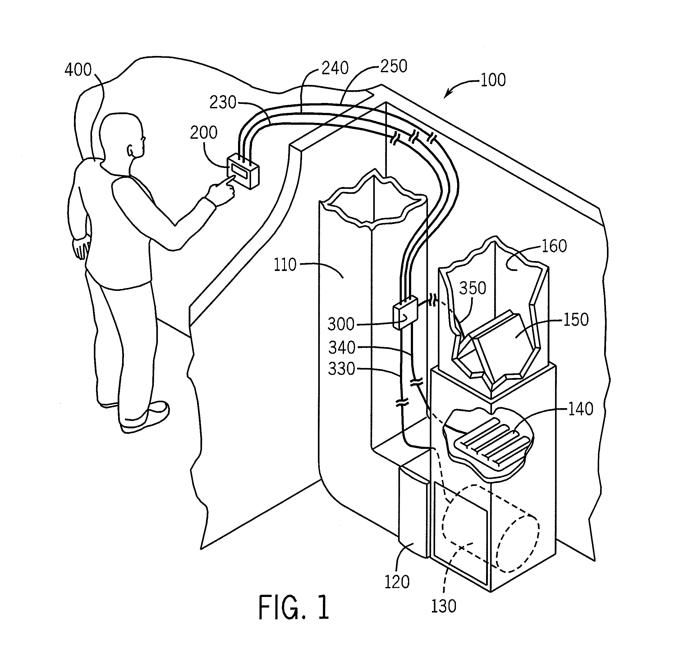
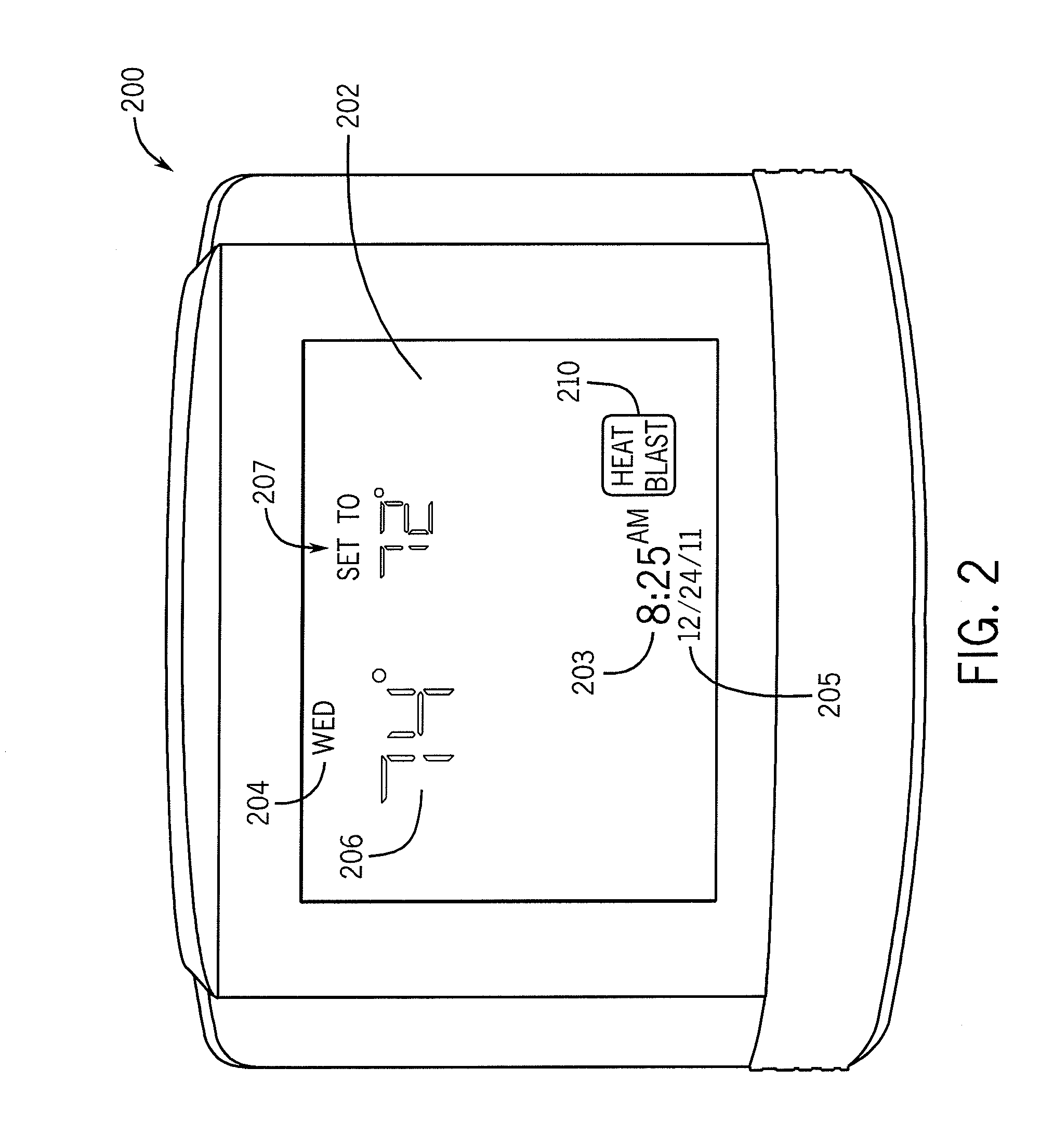
[0018]The invention illustrated in the Figures and disclosed herein is generally directed to an HVAC system 100, and a control system 500, 600 and method for the adjustment of ambient air temperature in an environment to improve the short term comfort of a user. For ease of discussion and understanding, the following detailed description will at times refer to the operation of an HVAC control program to improve the short term comfort of a user in association with a heat mode or heat cycle. It should be appreciated that “heat mode” or “heat cycle” is provided for purposes of illustration, and the HVAC control program to improve the short term comfort of a user may be used in association with any number of HVAC control situations, including, but not limited to, a cooling mode or cooling cycle. In addition, it should be appreciated that temperatures measured, targeted or otherwise used in association with HVAC system 100 or control system 500, 600 may be in Fahrenheit units, Celsius un...


PUM


Abstract

A system for the temporary adjustment of ambient temperature in an environment to improve the short term comfort of a user is also provided. The system includes an HVAC system including a unit to condition air, the HVAC system in operable communication with the environment to provide conditioned air, a thermostat in communication with the HVAC system, the thermostat adapted to measure the ambient temperature of the environment and to provide control instructions to the HVAC system, and a control module residing on the thermostat, the control module adapted to execute program parameters upon activation of a program execution button. A method for temporarily adjusting an ambient temperature of an environment regulated by an HVAC system is also provided.

Description

FIELD OF THE INVENTION[0001]The present invention relates to heating, ventilation, and air conditioning (HVAC) systems. More specifically, the present invention relates to a system and method for the adjustment of ambient air temperature in an environment by operation of an HVAC control program.BACKGROUND[0002]Thermostats and related programmable controls for an HVAC control system are generally known in the art. A thermostat is a component of an HVAC control system which can regulate the ambient temperature of an environment to be near a desired set point temperature. In addition, a thermostat may also include programmable controls for the HVAC system. For example, the thermostat may have one or more programmable settings which provide a desired ambient temperature target for a period of time. The period of time may further be associated with a specified day. This enables a user of a thermostat to input program settings which balance different factors. For example, the user may pro...

Claims


Application Information

Patent Timeline
IPC IPC(8): G05D23/00
CPCG05D23/1902F24F2011/0091F24F11/0012F24F11/30F24F2110/10F24F11/52F24F11/61F24F11/76F24F11/46F24F11/523F24F11/63F24F11/56
Inventor SCHUMAN, DANIEL C.
Owner RES PRODS
Learn More