
Motion analysis system and motion analysis method

a technology of motion analysis and motion, applied in the field of motion analysis system and motion analysis method, can solve the problems of difficult to precisely synchronize the time of the output from the plurality of sensors, limited analysis information of images captured by cameras, etc., and achieve the effect of synchronizing the time of outpu

Active Publication Date: 2013-07-25
SEIKO EPSON CORP
View PDF3 Cites 47 Cited by
  • Summary
  • Abstract
  • Description
  • Claims
  • Application Information

AI Technical Summary

Benefits of technology

The invention provides a motion analysis system and method that can reliably synchronize output from multiple sensors even when the sensors receive synchronization signals in chronological order. This is achieved by generating a reference synchronization signal at an average intermediate time obtained from multiple pairs of synchronization signal groups. The system can also set a reference synchronization flag to one of the sampling data items to output, thereby avoiding the need to transmit unnecessary data to the host terminal. These technical improvements enhance the accuracy and efficiency of motion analysis.

Problems solved by technology

As a method of evaluating a motion of an object such as a golf swing, an image captured by a camera has limited analysis information.
At this time, when a synchronization signal is transmitted from a host terminal to the plurality of sensors in chronological order, for example, since the time to receive the synchronization signal for the plurality of sensors is shifted, it is difficult to precisely synchronize the time of the output from the plurality of sensors.

Method used


Image

  • Motion analysis system and motion analysis method
  • Motion analysis system and motion analysis method
  • Motion analysis system and motion analysis method

Examples


modification example

3. Modification Example

[0063]The embodiment has been described in detail as described above, however, a person skilled in the art may easily understand that various modifications can be performed in a range without departing from the new matter and the effects of the invention. Accordingly, all of the modification examples are assumed to be included in a range of the invention.

[0064]For example, the measurement target object of the invention can be suitably applied to exercise equipment such as a golf club, a tennis racket, or the like; however it is not limited thereto.

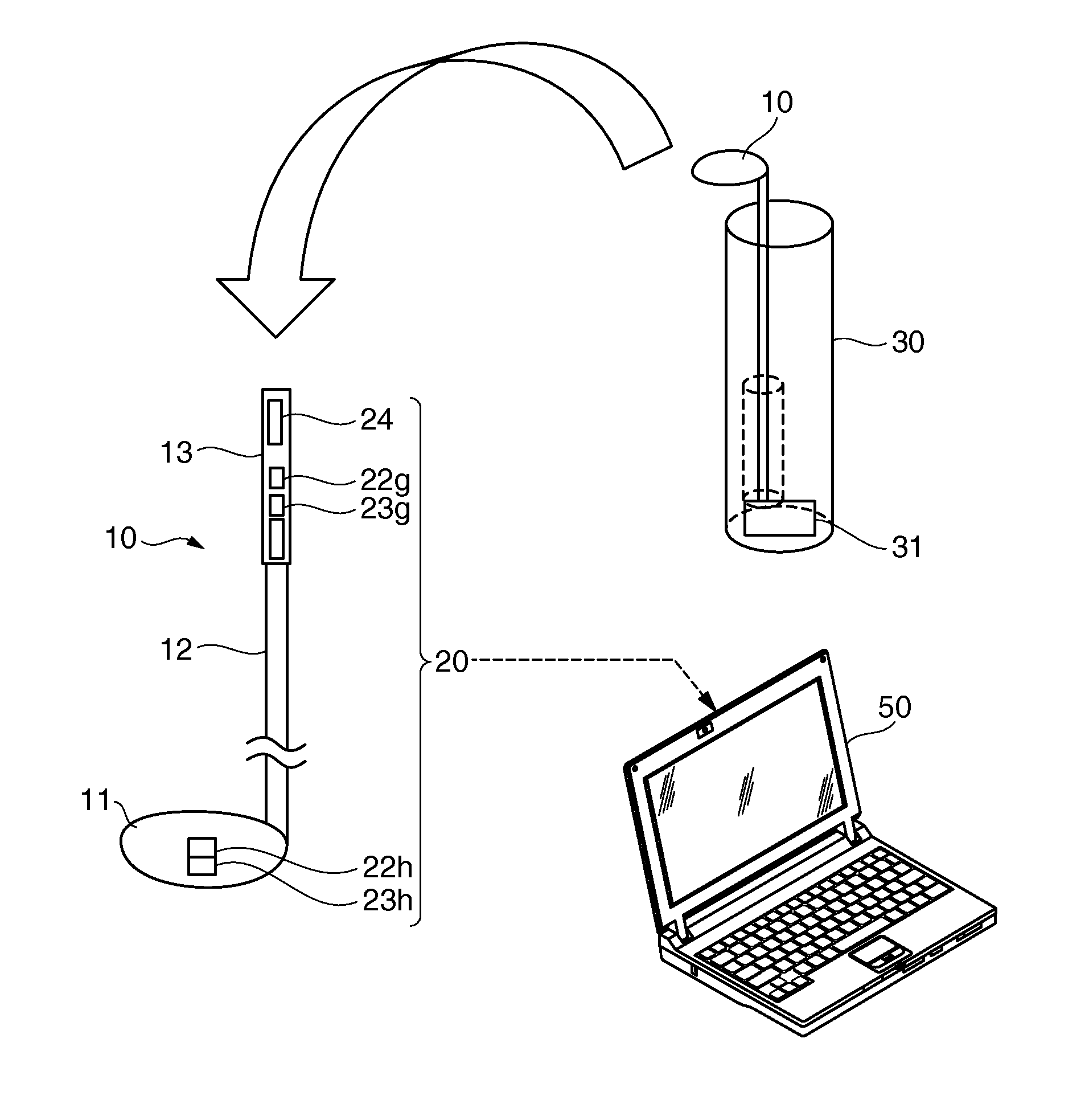
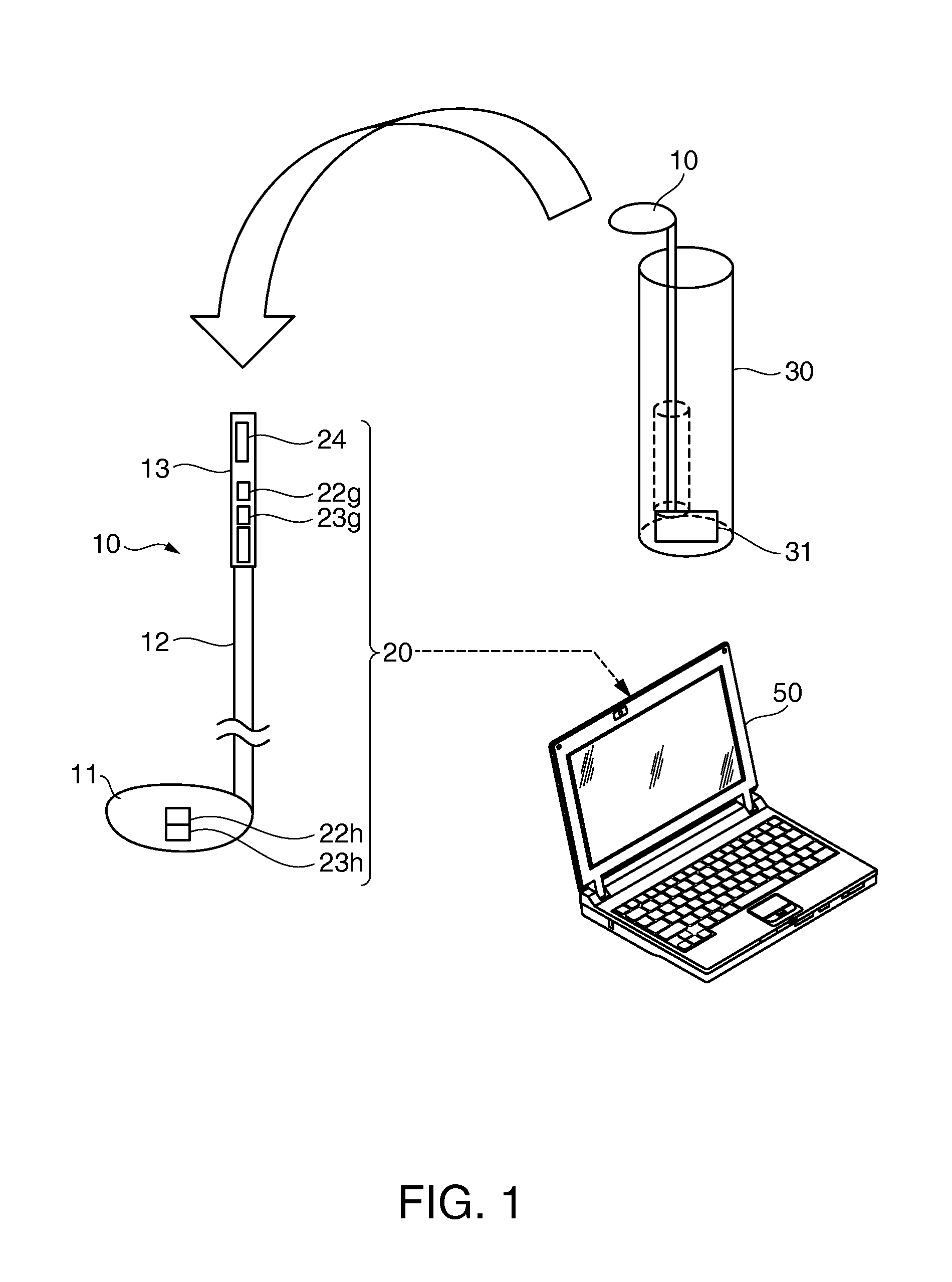
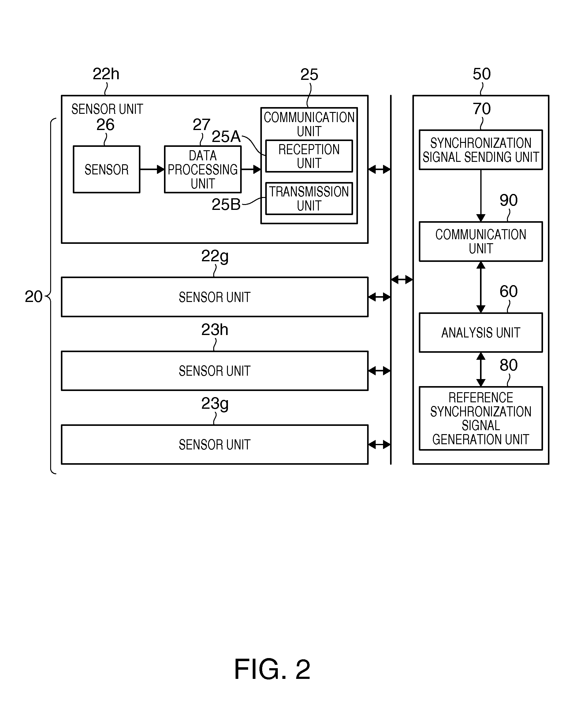
[0065]FIG. 7 shows an example of providing the reference synchronization signal generation unit 80 in each of the first to fourth sensor units 22h, 22g, 23h, and 23g. In this case, the data processing unit 50 of each of the plurality of sensor units 22h, 22g, 23h, and 23g can output the sampling data shown in FIG. 6, not FIG. 5. That is, when the reference synchronization signal generation unit 80 is provided in each...


PUM


Abstract

A motion analysis system includes first to N-th (N is an integer of 2 or more) sensor units which is attached to an object, an analysis unit which obtains a plurality of items of sampling data output from the sensor units, to analyze a motion of the object, a synchronization signal sending unit which transmits a first synchronization signal group including N first synchronization signals in order from the first to the N-th sensor unit, and transmits a second synchronization signal group including N second synchronization signals in order from the N-th to the first sensor unit, with respect to sensor unit, and a reference synchronization signal generation unit which generates a reference synchronization signal which is to be a reference with respect to the first to N-th sensor units, based on the first and second synchronization signal groups received by sensor unit.

Description

BACKGROUND[0001]1. Technical Field[0002]The present invention relates to a motion analysis system and a motion analysis method which analyze a motion of an object such as a golf swing or the like.[0003]2. Related Art[0004]As a method of evaluating a motion of an object such as a golf swing, an image captured by a camera has limited analysis information. Thus, it is proposed to analyze the swing by providing a plurality of sensors such as acceleration sensors, Gyro sensors, and the like on a golf club as disclosed in JP-A-2008-73210.[0005]A plurality of sensors are attached onto an object for analyzing motion of the object. In JP-A-2008-73210, Gyro sensors and acceleration sensors are attached onto a shaft portion and a head portion of a golf club.[0006]As described above, in order to analyze motion of an object based on output from the plurality of sensors attached to the object, it is necessary to synchronize the time of the output from the plurality of sensors. This is because it ...

Claims


Application Information

Patent Timeline
IPC IPC(8): G01D18/00G06F17/00A63B53/00A63B102/32G01D21/00G01P3/44G01P7/00G08C15/06
CPCA63B24/0003G01P1/127G01P1/12G06F17/00G01D18/00A61B5/6895A61B5/1121A61B5/1128
Inventor NOMURA, KAZUO
Owner SEIKO EPSON CORP
Learn More