Computer system, virtual server alignment method, and alignment control apparatus

a virtual server and alignment control technology, applied in computing, instruments, electric digital data processing, etc., can solve the problems of inability to meet the quality of service (qos) required by users, inability to consider the amount of communication bandwidth, and inability to realize power saving, etc., to achieve a more appropriate alignment and a more convenient effect of virtual machines

Inactive Publication Date: 2013-07-25
HITACHI LTD
View PDF2 Cites 38 Cited by
  • Summary
  • Abstract
  • Description
  • Claims
  • Application Information

AI Technical Summary

Benefits of technology

[0015]This invention has been made to solve the above-mentioned problems. Specifically, exemplary embodiments of this invention provide a system, method, and apparatus for selecting a route that can avoid dropping of a large amount of packets considering a communication status of a router included in a movement route.
[0017]According to the exemplary embodiments of this invention, the communication route of the movement destination may be selected from among the candidate routes based on the occurrence probability of packet drop, which is the degree of risk that packet drop occurs, and hence a safer and more appropriate alignment of the virtual machines may be realized.

Problems solved by technology

However, while Japanese Patent Application Laid-open No. 2011-82799 describes controlling the virtual server alignment by allocating resources optimally, consideration is not given to the amount of communication bandwidth of a flow connected to the virtual server, that is, the probability of packet drop in the router included in the movement route.
In this case, retransmission of data occurs, and hence power saving cannot be realized and the quality of service (QoS) required by the users cannot be satisfied.

Method used


Image

  • Computer system, virtual server alignment method, and alignment control apparatus
  • Computer system, virtual server alignment method, and alignment control apparatus
  • Computer system, virtual server alignment method, and alignment control apparatus

Examples


first embodiment

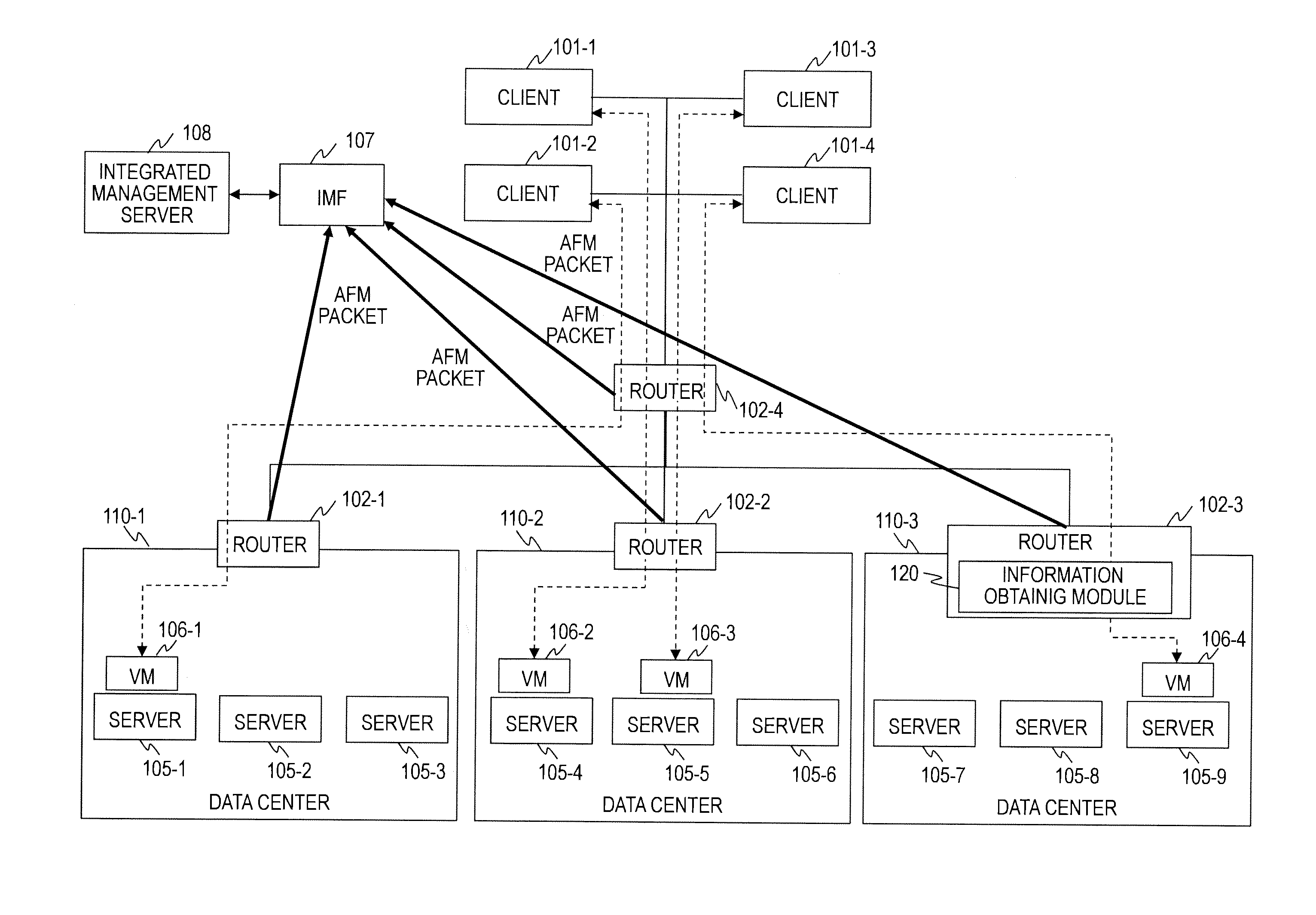
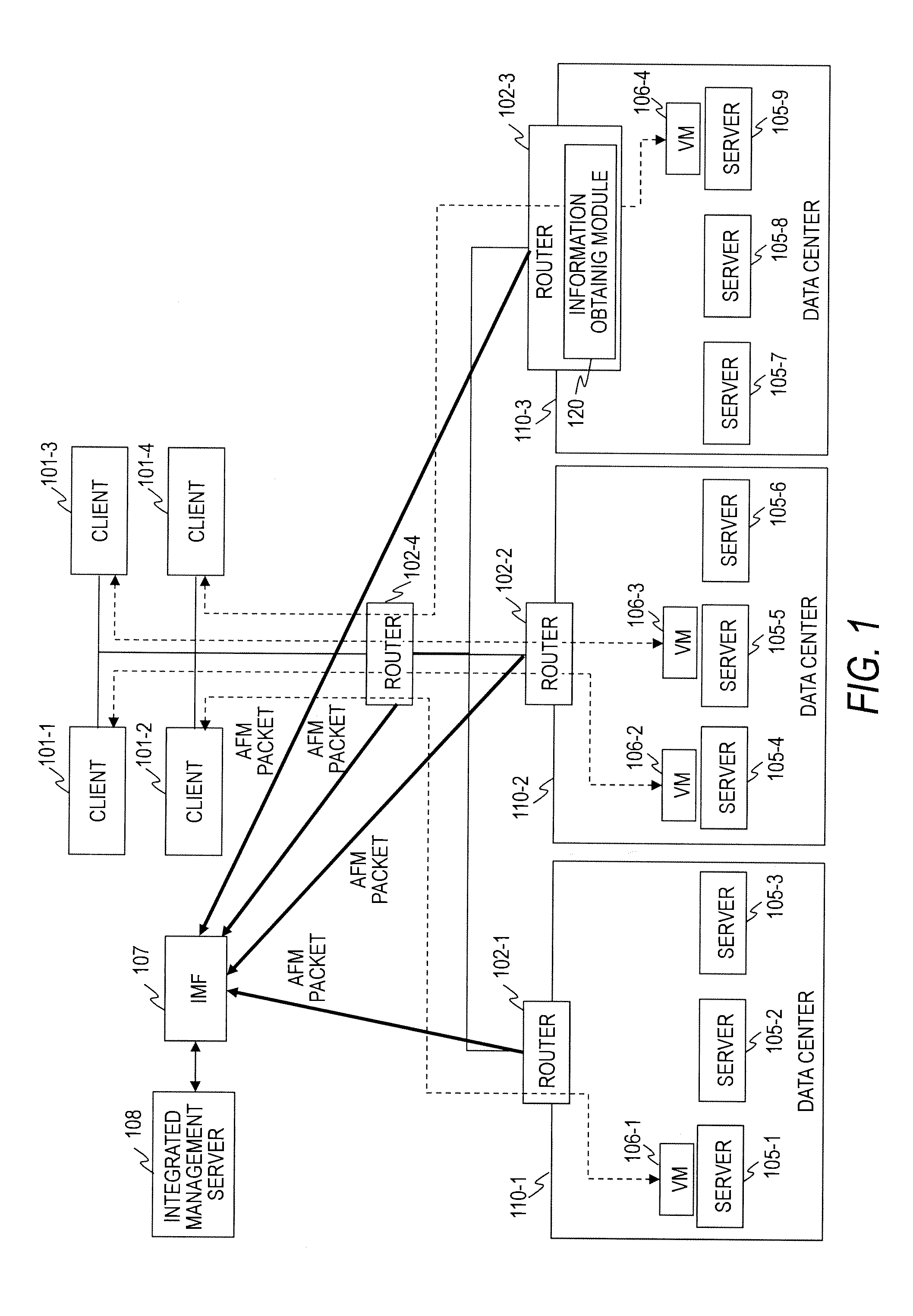
[0031]FIG. 1 is an explanatory diagram illustrating a configuration example of a computer system according to a first embodiment of this invention.

[0032]The computer system according to the first embodiment includes clients 101, routers 102, integrated mining of flow (IMF) 107, an integrated management server 108, and data centers 110. It should be noted that each of the data centers 110 includes a plurality of servers 105.

[0033]It should be noted that the clients 101, the routers 102, the integrated mining of flow (IMF) 107, the integrated management server 108, and the data centers 110 are communicably connected to one another.

[0034]In this embodiment, the integrated management server 108 estimates the future traffic status based on the current status of the traffic (amount of communication) and controls alignment of virtual servers (VMs 106). Therefore, in order to identify the traffic statuses of the routers 102 included in the routes connecting the routers 102 and the VMs 106, ...

second embodiment

[0158]A second embodiment of this invention is described. It should be noted that differences from the first embodiment are mainly described.

[0159]A configuration of a computer system, and configurations of the IMF 107 and the integrated management server 108 according to the second embodiment are the same as those of the first embodiment, and hence description thereof is omitted.

[0160]The second embodiment is different in the method of calculating the occurrence probability of packet drop. Specifically, the occurrence probability of packet drop is calculated by Equation (2) below. σ1 represents the insertion bandwidth, that is, the standard deviation in the traffic distribution of the flow in the communication route connected to the VM 106 before the movement.

Potency=exp(-(LineLimit-(TotalBandwidth+InsertionBandwidth))22*(σ+σ1)2)(2)

[0161]At this time, the IMF 107 determines the traffic distribution in the flow as the movement target and further calculates the standard deviation in ...

third embodiment

[0163]A third embodiment of this invention is described. It should be noted that differences from the first embodiment are mainly described.

[0164]A configuration of a computer system, and configurations of the IMF 107 and the integrated management server 108 according to the third embodiment are the same as those of the first embodiment, and hence description thereof is omitted.

[0165]The third embodiment has a feature in that, in a case where an appropriate communication route cannot be determined in Step S1006 even in a case where Equation (1) or Equation (2) is used, the communication route is determined based further on the value using Equation (3) below.

Potency=(TotalBandwidth+InsertionBandwidth)LineLimit*1(1-DropRatio)(3)

[0166]In the equation, “Drop Ratio” represents a packet drop rate. The packet drop rate is a value that can be obtained from the router 102.

[0167]Examples of the case where the appropriate route cannot be determined even when Equation (1) or Equation (2) is use...


PUM


Abstract

A computer system comprising a plurality of clients, a plurality of servers, a plurality of routers, an analysis device for monitoring communication statuses of the plurality of routers, and a management computer for controlling alignment of a virtual machine operating on each of the plurality of servers, the each of the plurality of routers including an information obtaining module for obtaining communication information for each flow, the analysis device including: an analysis module for analyzing the communication information; and a probability calculation module for calculating a occurrence probability of packet drop, the management computer including: a load estimation module for estimating a load for each of communication routes for moving the virtual machine; and an alignment determination module for determining, based on the occurrence probability of packet drop, the communication route of the movement destination.

Description

CLAIM OF PRIORITY[0001]The present application claims priority from Japanese patent application JP 2012-8645 filed on Jan. 19, 2012, the content of which is hereby incorporated by reference into this application.BACKGROUND OF THE INVENTION[0002]This invention relates to control of virtual server alignment. In particular, this invention relates to a system, method, and apparatus for controlling virtual server alignment in consideration of a network load in virtual servers.[0003]Cloud computing has recently been proposed as a service for providing all kinds of computer resources. Through use of the cloud computing, it is possible to provide computer resources, which are owned by companies that provide services to users, from different locations to the users. Through introduction of the cloud computing, it is possible to provide merits in terms of speed, price, and the like.[0004]One problem in the cloud computing is how to lower power consumption. The services using the cloud computin...

Claims


Application Information

Patent Timeline
Patent Type & Authority Applications(United States)
IPC IPC(8): G06F9/455
CPCG06F9/455H04L41/0213H04L43/18H04L43/0817H04L41/40
Inventor SHIMOKAWA, ISAOTARUI, TOSHIAKISUZUKI, TOSHIAKI
Owner HITACHI LTD
Why Eureka
Try Eureka