Method for climate control in buildings

Inactive Publication Date: 2013-08-01
BIOLOGISCHE INSEL LOTHAR MOLL
View PDF0 Cites 3 Cited by
  • Summary
  • Abstract
  • Description
  • Claims
  • Application Information

AI Technical Summary

Benefits of technology

[0042]The moisture-variable air-tightness, which is used in these structures, also does not offer protection anymore when moisture enters into the structure due to the smallest leaks and the natural static pressure differences, in particular also in the case of exterior shading or also in the case of diffusion-inhibiting interior component layers, both of which prevent a back diffusion of the moisture located in the structure through the moisture-variable vapor barr

Problems solved by technology

The main cause of structural damages is the leakiness of the building shell, in particular of the interior building shell, which is also called air-tightness.
A moisture increase within the structure above 6

Method used


Image

  • Method for climate control in buildings
  • Method for climate control in buildings
  • Method for climate control in buildings

Examples


Embodiment Construction

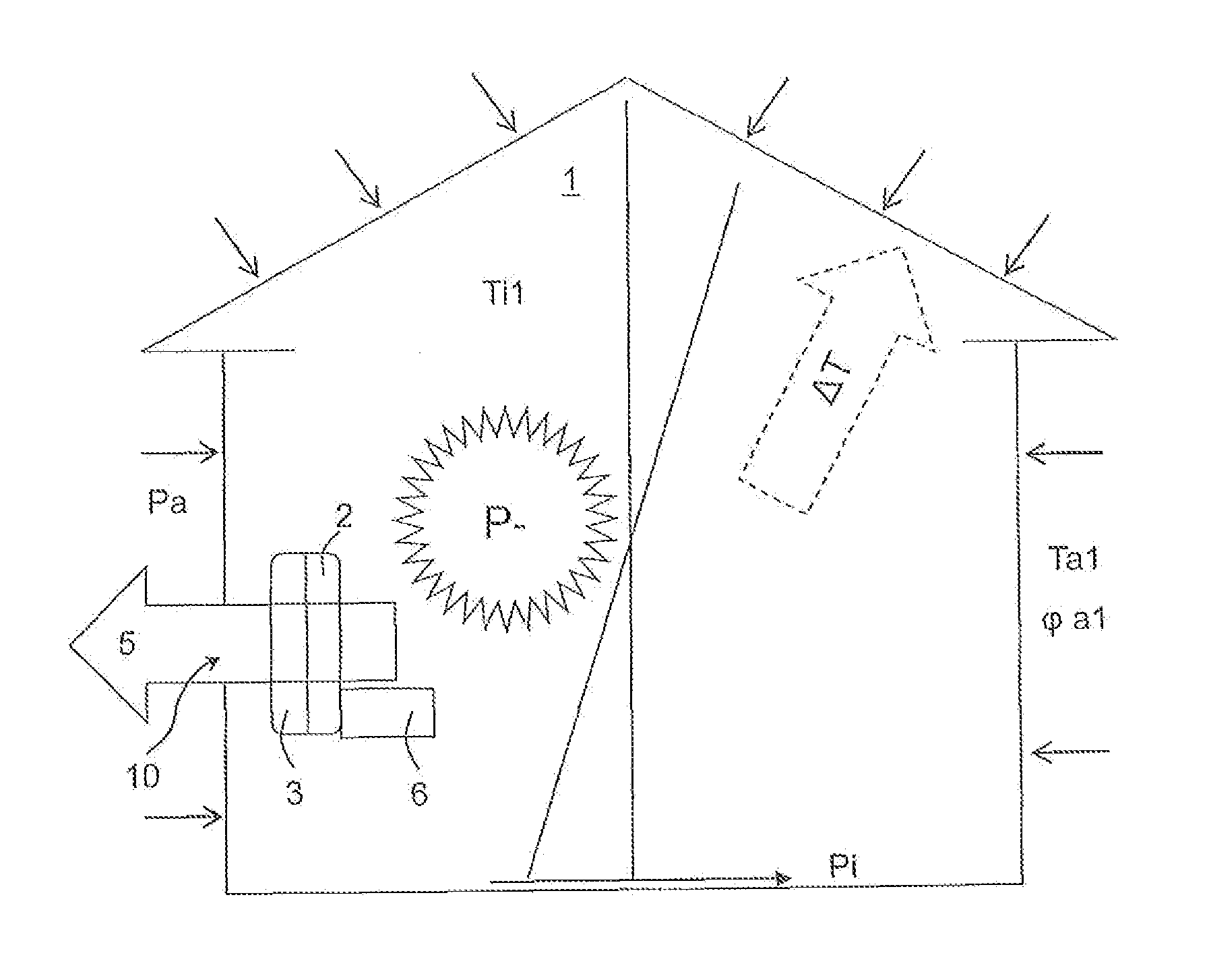
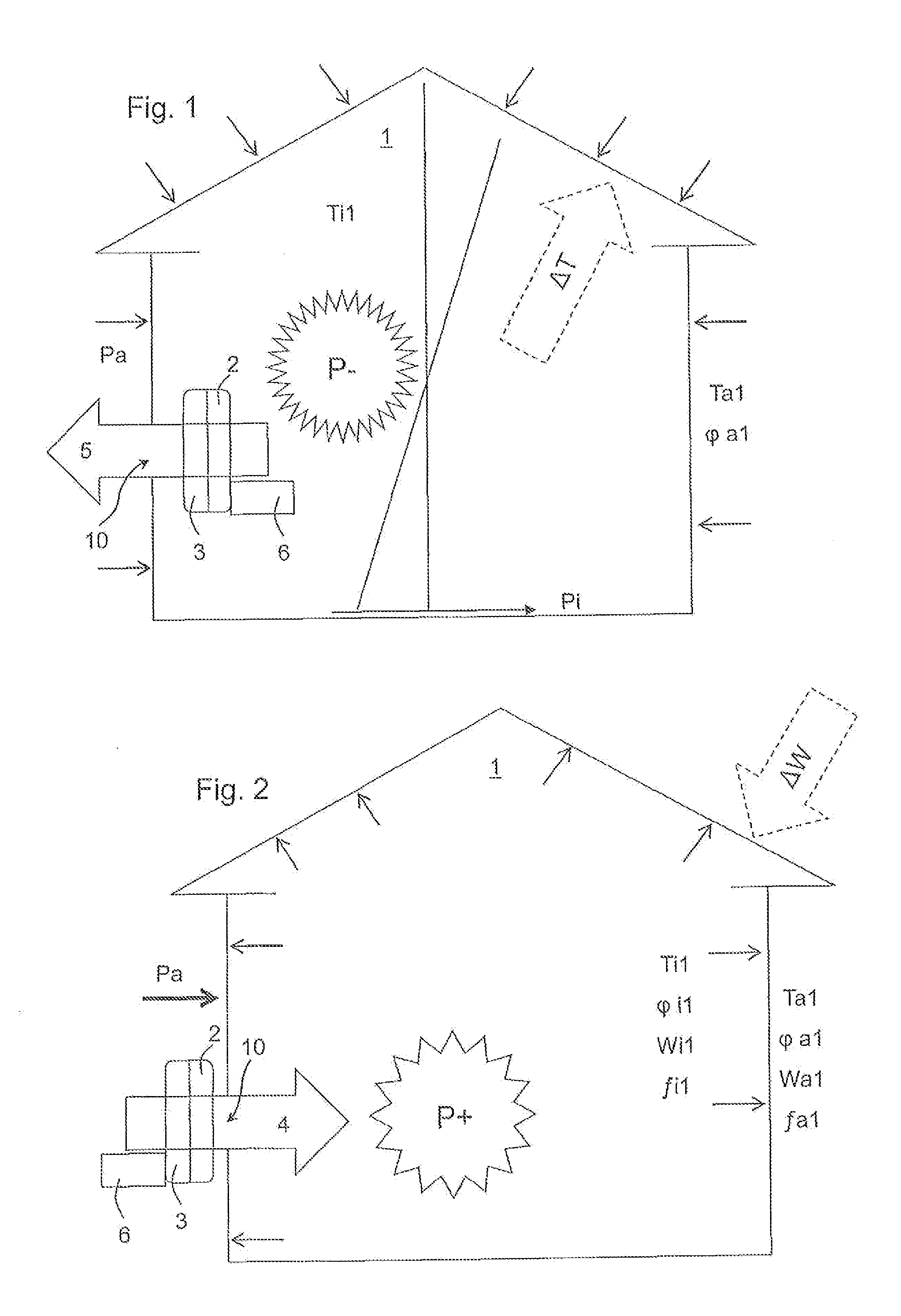
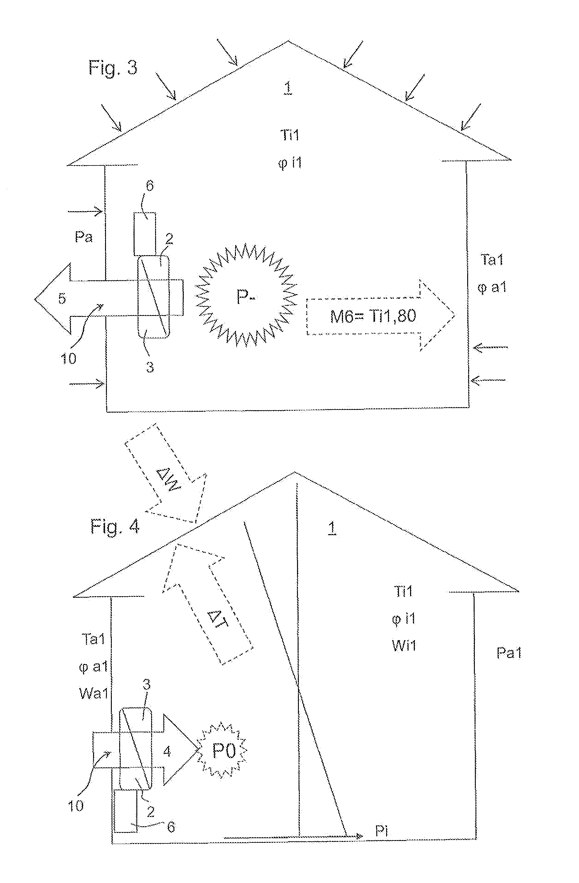
[0054]In practice, a plurality of the afore-described variables are measured directly at a building 1 by means of corresponding sensors or are calculated by means of a corresponding logic in the regulation.

[0055]The following example is to clarify this. Assumption:

Ta = 12°φa = 0.8Ti = 18° C.φ1 = 0.5Building height = 5 mmwind speed = 3 m / s

It follows from this:[0056]1) A partial water vapor pressure difference from outside to inside of 91 Pascal.[0057]2) A pressure drop of the internal building pressure Pi of 1.2 Pascal and an internal building pressure Pi in the lower range of −0.6 Pascal. An overpressure P+ of 5.6 Pascal results through the wind.[0058]3) A temperature drop of 6 Kelvin from the inside to the outside.

[0059]It is to now be determined, how the air flow is to be forced through the ventilation system 2. When considering only the critical relative humidity of 0.8, it can then be determined that the inside air would reach a critical moisture value when passing through the i...


PUM


Abstract

A method for climate control in buildings 1, having a ventilation system 2 with at least a control and regulation unit 6 and an air-guide unit, wherein the ventilation system 2 generates, by means of a separate building opening 10, at least one regulated inflow stream 4 which flows into the building 1 and/or at least one regulated outflow stream 5 which flows out of the building. The insulation and structure of the building 1 should be kept free of condensate. To this end, provision is made for at least one current value for a temperature Ti and/or a corresponding absolute internal atmospheric moisture level ∫il and/or a relative atmospheric moisture level φi or a partial steam pressure Wi in the interior of the building 1 and at least one current value for a temperature Ta and/or a corresponding absolute external atmospheric moisture level ∫al and/or a relative atmospheric moisture level φa or a partial steam pressure Wa outside the building 1 to be ascertained. The respectively measured values are supplied to the control and regulation unit 6. An overpressure or an underpressure or no pressure is generated by the air-guide unit in the building 1 as a function of the magnitude of the difference between the values.

Description

FIELD OF THE INVENTION[0001]The invention relates to a measuring and regulating method for ventilating a building, comprising at least one ventilation system and at least one control and regulating unit, wherein the ventilation system generates at least one regulated supply air stream, which flows into the building via at least one separate building opening and / or at least one regulated exhaust air stream, which flows out of the building. Such methods are typically coupled to a heat recovery.BACKGROUND OF THE INVENTION[0002]DE 20 2007 018 549 U1 describes a heat recovery module for the central ventilation and deaeration of buildings and homes. The basic principle of the application relating to this technology will be explained in detail below.[0003]Energy savings goals for the building area and growing demands on an increased tightness of the outer building shell lead to an increased use of building technology measures, which serve for the controlled, automated home ventilation. The...

Claims


Application Information

Patent Timeline
IPC IPC(8): F24F11/00F24F11/04F24F7/007F24F11/76
CPCF24F7/007F24F11/0001F24F11/053F24F11/04F24F2011/0005F24F11/0012F24F11/0015F24F2011/0004F24F11/30F24F2110/10F24F2110/20F24F11/74F24F11/76F24F11/46F24F11/62F24F11/755
Inventor MOLL, LOTHAR
Owner BIOLOGISCHE INSEL LOTHAR MOLL
Why Eureka
Try Eureka