Vehicle reinforcing structure

a technology for reinforcing structures and vehicles, applied in the direction of superstructure sub-units, roofs, vehicle components, etc., can solve problems such as vehicle weight increase, and achieve the effects of preventing local stress concentration, preventing members from breaking, and preventing breakag

Inactive Publication Date: 2013-08-01
SUZUKI MOTOR CORP
View PDF12 Cites 2 Cited by
  • Summary
  • Abstract
  • Description
  • Claims
  • Application Information

AI Technical Summary

Benefits of technology

[0010]Moreover, in the aforementioned configuration, the second welded part extends in the vehicle width direction while the load applied to the reinforcing member acts diagonally toward the vehicle front. That is, the load is also applied to the second welded part diagonally. As described above, the first and second welded parts are not arranged in-line in the vehicle width direction and extend in mutually different directions, thus making it possible to prevent a local stress concentration on the first and second welded parts and the reinforcing member itself and prevent breakage.
[0011]As described above, the load can be absorbed by the reinforcing member in a highly rigid manner, thus making it possible to prevent the members from breaking when the vehicle is subjected to an impact. In particular, it is possible to suitably prevent deformation of the roof member that often has less rigidity than the pillar member.
[0012]The vehicle reinforcing structure may further include a level difference part within the area of the reinforcing member, wherein the reinforcing member and the extension part or roof member are curved together in both the vehicle width direction and the vehicle front-rear direction in the level difference part. This configuration makes positioning easy when attaching the members and thus makes it possible to reduce labor.
[0013]The first welded part may be provided in a place that is within the level difference part and that is where the reinforcing member and the extension part are in surface-contact with each other in the vehicle width direction. This makes it possible to prevent a stress concentration on the first welded part when a load is generated in the vehicle width direction and prevent the first welded part from breaking
[0014]The roof member may include a roof outer panel that is formed from sheet metal and disposed on the vehicle exterior side and a roof sub-member that is formed from sheet metal and disposed on the vehicle interior side of the roof outer panel so as to extend in the vehicle width direction, and the second welded part may be provided in a double contact area in which the roof outer panel and the roof sub-member are in contact. In this way, the second welded part is provided in the double contact area that is particularly a highly rigid portion of the roof member, thus making it possible to suitably absorb the load transmitted via the reinforcing member and prevent breakage.
[0015]As described above, a vehicle reinforcing structure that has a simple configuration and that makes it possible to enhance rigidity in the area around the border between the side body and the roof can be provided.

Problems solved by technology

However, the pillar member is thick and is likely to be heavy, resulting in a vehicle weight increase if a wide extension part is provided.

Method used


Image

  • Vehicle reinforcing structure
  • Vehicle reinforcing structure
  • Vehicle reinforcing structure

Examples


Embodiment Construction

[0022]Preferred embodiments of the present invention will now be described in detail below in reference to the accompanying drawings. Dimensions, materials, specific numerical values, etc. provided in the embodiments are merely illustrative to help understand the invention, and are not to limit the present invention unless indicated otherwise. In the specification and the drawings, elements that have essentially the same function or configuration are given the same numerical references to avoid repetitions in the description, and elements that are not directly related to the present invention are not shown in the drawings.

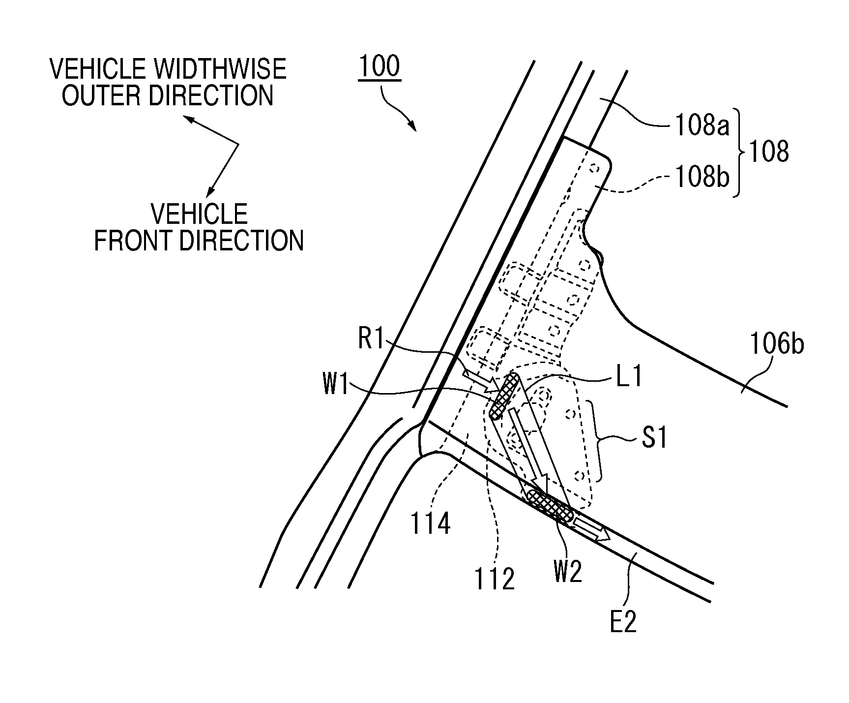
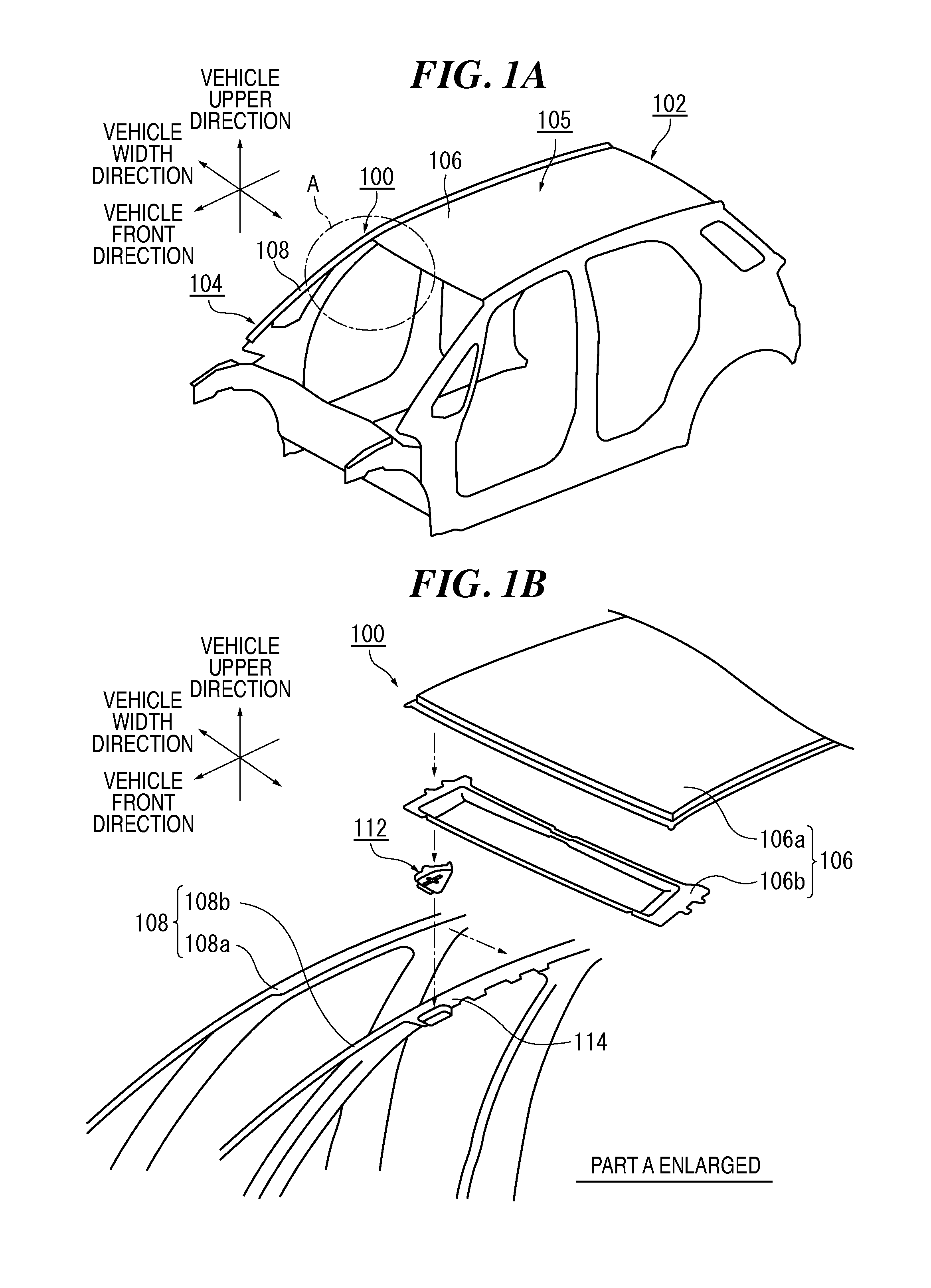
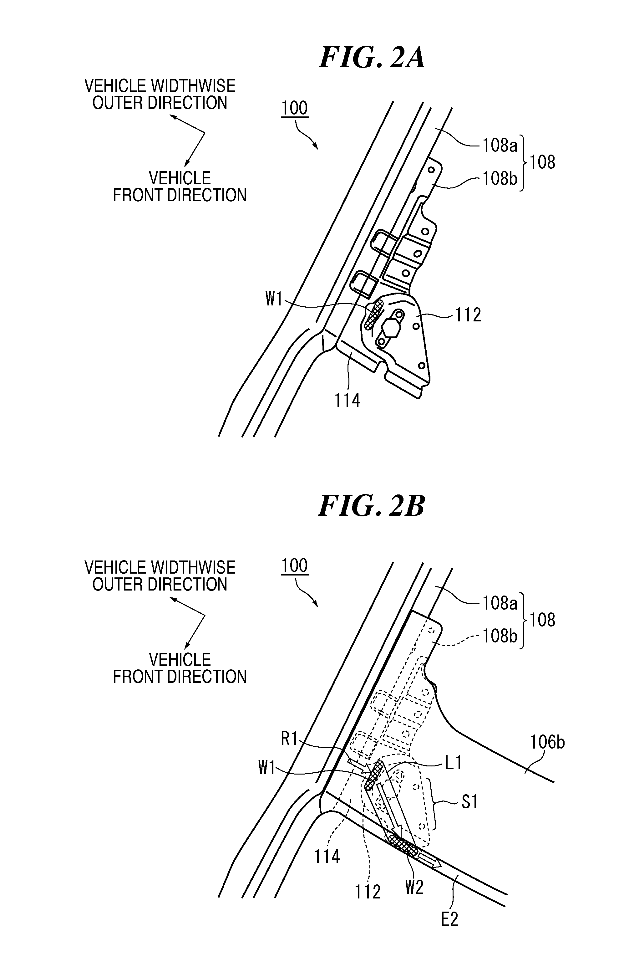
[0023]FIGS. 1A and 1B are diagrams showing a vehicle reinforcing structure 100 of this embodiment. FIG. 1A schematically shows fundamental structures of a vehicle 102 to which the vehicle reinforcing structure 100 is applied.

[0024]In the vehicle 102 shown in FIG. 1A, the vehicle reinforcing structure 100 of this embodiment reinforces the area around the border betw...


PUM


Abstract

A vehicle reinforcing structure includes a roof member, a pillar member that has in its upper part an extension part that extends along the roof member, and a reinforcing member that is joined so as to bridge the extension part and the roof member. The reinforcing member has a first welded part welded to the extension part, and a second welded part welded to a front edge of the roof member. The first welded part and the second welded part are provided such that an imaginary area created with straight lines that connect the respective edges of the welded parts substantially fits within the area of the reinforcing member. The reinforcing member further has an open area that is not in contact with either the pillar member or the roof member on the vehicle interior side of the first welded part on the rear side of the second welded part.

Description

CROSS-REFERENCE TO RELATED APPLICATION(S)[0001]This application claims the benefit of and priority to Japanese Patent Application No. 2012-001213, filed on Jan. 6, 2012 and entitled “Vehicle Reinforcing Structure”, which is assigned to the assignee hereof and which is incorporated herein by reference.FIELD[0002]The present invention relates to a vehicle reinforcing structure that reinforces the area around a border between a side wall and a ceiling of a vehicle.BACKGROUND[0003]In order to secure rigidity, fundamental structures of a vehicle, such as a side body and a roof, are configured with a plurality of panel members placed one on another. It is known that, when a vehicle is subjected to an unexpected impact, a load is likely to be concentrated in the area around the border between the side body and the roof among such fundamental structures. In particular, the side body needs to support the roof and is thus often set to have high rigidity, and it is confirmed through roof crash...

Claims


Application Information

Patent Timeline
Patent Type & Authority Applications(United States)
IPC IPC(8): B62D25/06
CPCB62D25/06
Inventor NAKAAKI, KAZUYOSHI
Owner SUZUKI MOTOR CORP
Why Eureka
Try Eureka