Electronically-steered ku-band phased array antenna comprising an integrated photonic beamformer

a phased array antenna and beamformer technology, applied in the manufacture of antenna arrays, electrical appliances, antennas, etc., can solve problems such as difficulty in producing antennas, and achieve the effect of avoiding some of the costs and drawbacks

Active Publication Date: 2013-08-01
UNIVSERSITEIT TWENTE
View PDF6 Cites 20 Cited by
  • Summary
  • Abstract
  • Description
  • Claims
  • Application Information

AI Technical Summary

Benefits of technology

[0005]The present invention provides an electronically-steered phased-array antenna that avoids some of t

Problems solved by technology

It is quite challenging to produce an antenna system having multi-gigahertz instantaneous bandwidth, compact form

Method used


Image

  • Electronically-steered ku-band phased array antenna comprising an integrated photonic beamformer
  • Electronically-steered ku-band phased array antenna comprising an integrated photonic beamformer
  • Electronically-steered ku-band phased array antenna comprising an integrated photonic beamformer

Examples


Embodiment Construction

[0040]The illustrative embodiment of the present invention is a phased-array receive antenna for Ku-band satellite transmission. It will be appreciated that substantially the same antenna architecture can be used to receive both higher and lower frequency-band transmissions. As will be appreciated by those skilled in the art, when used to receive transmissions of such other frequency bands, the size of the antenna elements will necessarily be different. Furthermore, the number of antenna elements required for the antenna is likely to be different than the illustrative embodiment. Additionally, the design of many of the electrical-domain processing elements may require alteration. After reading this specification, those skilled in the art will be able to make and use a phased-array antenna according to the present teachings as suitably modified for processing other frequency bands of signal transmissions.

[0041]Overview.

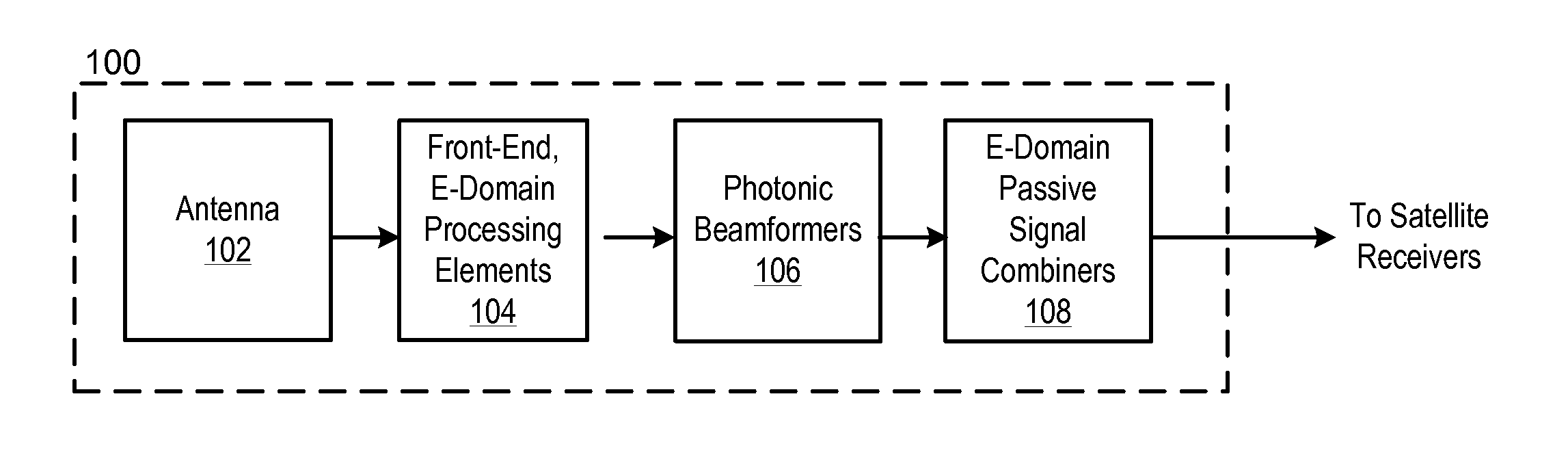
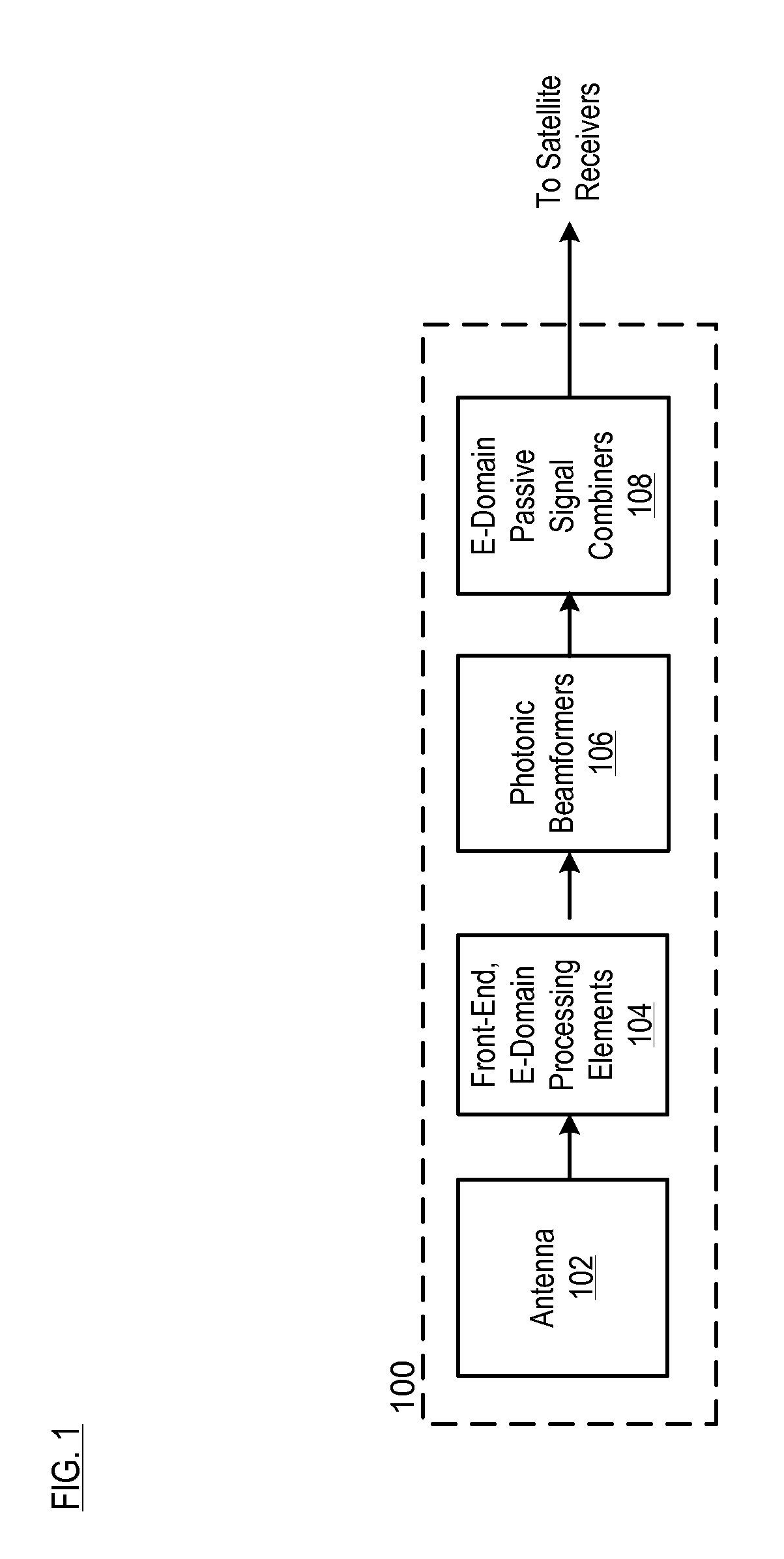
[0042]FIG. 1 depicts a high-level block diagram of a system archi...


PUM


Abstract

A phased-array antenna that includes a photonic beamformer is disclosed. In some embodiments, a front stage of electrical-domain processing applies a 16-to-1 signal-combination ratio, a single stage of photonic beamforming applies a 4-to-1 signal-combination ratio, and a passive, electrical-domain, signal combiner applies a 32-to-1 signal-combination ratio.

Description

CROSS REFERENCE TO RELATED APPLICATIONS[0001]This case claims the benefit of U.S. Patent Application 61 / 542,385, filed Oct. 3, 2011 (Attorney Docket: 130-001PROV) and is incorporated herein by reference.FIELD OF THE INVENTION[0002]The present invention relates to phased-array antennas.BACKGROUND OF THE INVENTION[0003]Mobile satellite communications, such as aeronautic / avionic satellite communications, require low-profile and light-weight antenna systems. The antenna systems used for such applications are usually electronically-steered phased arrays. Such systems desirably provide instantaneous reception of the full Ku-band (10.7-12.75 GHz), squint-free, and seamless beam steering, as well as polarization agility.[0004]It is quite challenging to produce an antenna system having multi-gigahertz instantaneous bandwidth, compact form factor, light weight, and large beam-scanning range via beam formers that use only electronics-based technologies. As a consequence, phased-array antenna s...

Claims


Application Information

Patent Timeline
IPC IPC(8): H01Q3/26
CPCH01Q3/2682H01Q21/0087H01Q3/2676
Inventor BEEKER, WILLEM PAULROELOFFZEN, CHRIS GERARDUS HERMANUSZHUANG, LEIMENGEIKENBROEK, JOHANNES WILHELMUSKLATSER, PAULVAN DIJK, PAULUS WILHELMUS LEONARDUS
Owner UNIVSERSITEIT TWENTE
Why Eureka
Try Eureka