Optical sensor and image forming apparatus

a technology of optical sensors and image forming apparatus, which is applied in the direction of optical radiation measurement, instruments, electrographic process, etc., can solve the problems of difficult to acquire the high quality image desired by the user, user may feel that the process is too complex to perform printing or the like, and cannot achieve high quality imag

Active Publication Date: 2013-08-01
RICOH KK
View PDF9 Cites 36 Cited by
  • Summary
  • Abstract
  • Description
  • Claims
  • Application Information

AI Technical Summary

Benefits of technology

[0017]The present invention solves or reduces one or more of the above problems.

Problems solved by technology

As a result, it is not possible to acquire a high quality image.
Also, if the user needs to set the fixing condition, the user may feel that it is too complex to perform printing or the like.
Moreover, if there is an error in the fixing condition set by the user, it is difficult to acquire the high quality image desired by the user.
Thus, there is a problem in which the surface of the recording paper or the like as the recording medium may become damaged.
In Japanese Laid-open Patent Application No. 2005-156380, it is possible to determine the smoothness or the like of the recording medium but it is difficult to determine the thickness or the like of the recording medium.
H11-249353, it is possible to roughly determine the recording medium, but it is not possible to determine the thickness or the like of the recording medium in detail.
H11-249353, it is possible to identify (determine) only a non-coated paper, a coated paper, and an OHP sheet but it is not possible to specify the name of the recording medium for a high quality image formation.
By mounting multiple sensors having different schemes, a size of the image forming apparatus is increased, and also, another problem is caused such as higher costs of manufacture.
Since the speckle pattern is different depending on portions illuminated by the light flux, dispersion of detection light at a light receiving part is caused and accuracy of identifying the printing paper may be degraded.

Method used


Image

  • Optical sensor and image forming apparatus
  • Optical sensor and image forming apparatus
  • Optical sensor and image forming apparatus

Examples


first embodiment

(Classification of Reflected Light)

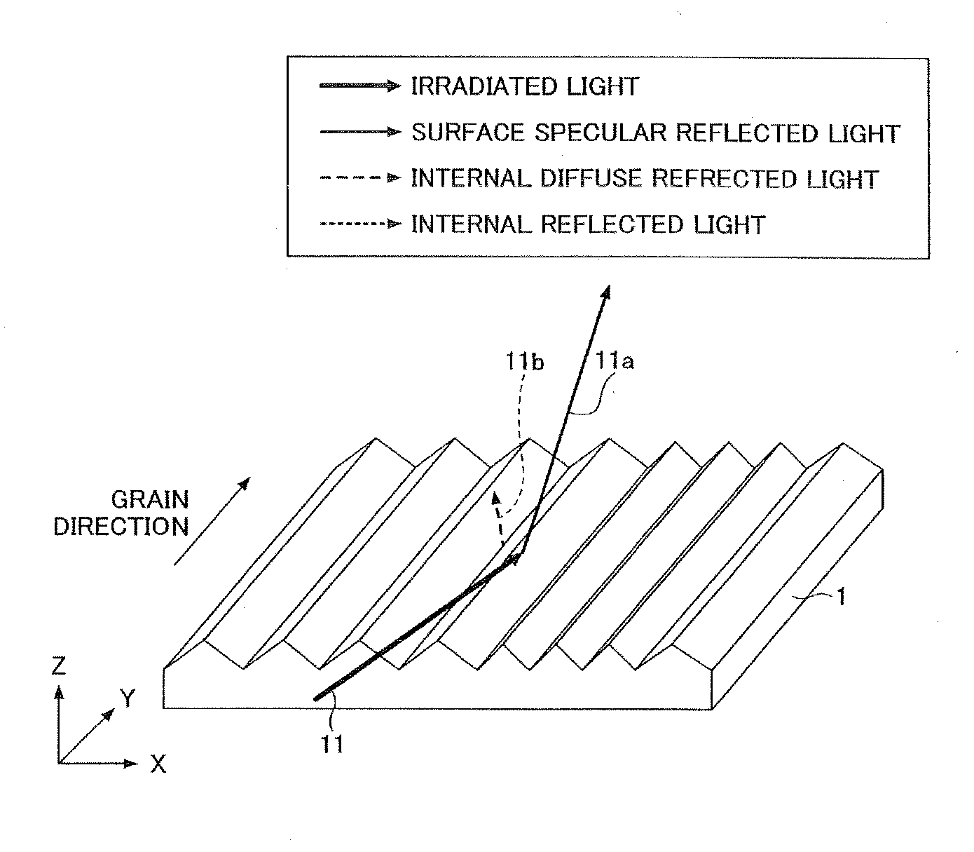
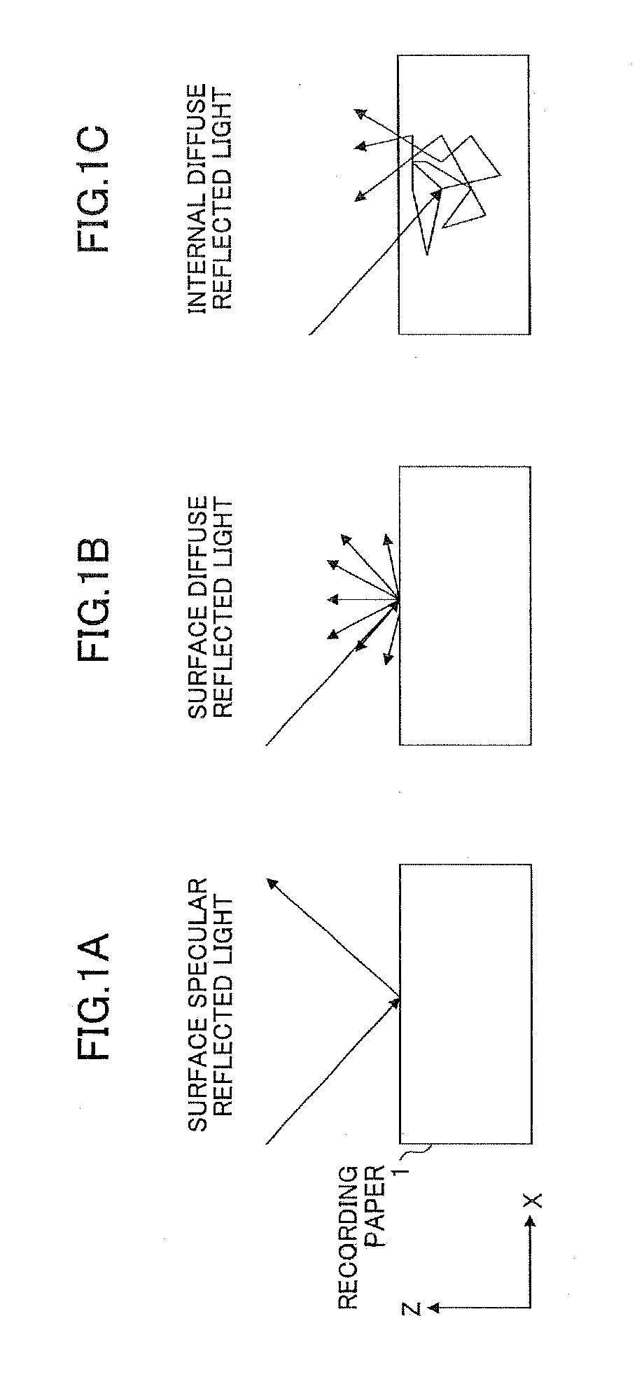
[0081]First, reflected light in a case of emitting light onto a recording medium such as a recording paper or the like will be described with reference to FIG. 1A, FIG. 1B, and FIG. 1C. In the case of emitting the light onto a recording paper 1 as the recording medium, it is possible to separate reflected light into light reflected from a surface of the recording paper 1 and light reflected inside the recording medium. Moreover, it is possible to separate the light reflected from the surface of the recording paper 1 into specular reflected light and diffuse reflected light. In the first embodiment, light specularly reflected from the surface of the recording paper 1 illustrated in FIG. 1A is described as a surface specular reflected light. Light diffusely reflected from the surface of the recording paper 1 is illustrated in FIG. 1B. In the first embodiment, a case of the recording medium being the recording paper 1 to which the light is illuminated...

second embodiment

[0143]Next, a second embodiment will be described with reference to FIG. 17 and FIG. 18. An optical sensor 1002 in the second embodiment includes two measurement systems similar to the optical sensor 1001 in the first embodiment. That is, the optical sensor 1002 includes the first measurement system 110 and the second measurement system 120. However, different from the first embodiment, the first measurement system 110 and the second measurement system 120 are arranged so that an angle between the light path of the light emitted from the first light emission system 111 and the light path of the light emitted from the second light emission system 121 is formed to be 90° on the XY plane. In other words, the systems 110 and 120 are arranged so that an angle between a component of the light emitted from the first light emission system 111 in which the component is parallel to the recording paper 100 and a component of the light emitted from the second light emission system 121 in which ...

third embodiment

[0149]Next, a third embodiment will be described. The third embodiment will be described with reference to FIG. 19. An optical sensor 1003 in the third embodiment includes two measurement systems similar to the first embodiment. That is, the optical sensor 1003 includes the first measurement system 110 and the second measurement system 120. However, different from the first embodiment, the first measurement system 110 and the second measurement system 120 are arranged so that the angle between the light path of the light emitted from the first light emission system 111 and the light path of the light emitted from the second light emission system 121 is formed to be 180° on the XY plane. In other words, the systems 110 and 120 are arranged so that an angle between a component of the light emitted from the first light emission system 111 in which the component is parallel to the recording paper 100 and a component of the light emitted from the second light emission system 121 in which...


PUM

PropertyMeasurementUnit
angleaaaaaaaaaa
angleaaaaaaaaaa
angle θ2aaaaaaaaaa

Abstract

In an optical sensor, a light emission system emits an irradiated light of a linear polarization in a first polarization direction toward a surface of a target object having a sheet shape from an incident direction which is inclined with respect to a normal direction of the surface. A first light detection system includes a first light detector arranged on a first light path of a specular reflected light, which is emitted from the light emission system and is specularly reflected from the target object. A second light detection system includes a second light detector arranged on a second light path of a diffuse reflected light which is diffusely reflected from an incident plane on the target object. The second light detector receives second light passed by an optical element which passes a linear polarization component of a second polarization direction perpendicular to the first polarization direction.

Description

TECHNICAL FIELD[0001]The present invention generally relates to an optical sensor and an image forming apparatus.BACKGROUND ART[0002]In an image forming apparatus using an electrophotographic method such as a digital copier, a laser printer, and the like, a toner image is transferred onto a recording medium such as a recording paper and is fixed by heating and pressurizing at a predetermined condition, thereby an image is formed on the recording medium such as the recording paper. In the image forming apparatus, a condition such as a heat amount, pressure, and the like to fix the toner image is considered. Especially, in a case of forming an image at high quality, it is needed to individually set a condition for fixing the toner image depending on types of the recording medium.[0003]An image quality for recording to the recording medium is greatly influenced by material, thickness, temperature, smoothness, a coating state, and the like. For example, regarding the smoothness, a fixin...

Claims


Application Information

Patent Timeline
Patent Type & Authority Applications(United States)
IPC IPC(8): G01N21/55G01N21/47
CPCG03G15/5029G01N21/4738G01N21/57G01B11/0625G01N21/21G01N21/55G01N33/34G03G15/04072G03G15/0409G03G15/0435G03G15/326G01B11/06G03G21/00G03G21/14G01N2021/4792G01N2201/06113G03G15/5062
Inventor OHBA, YOSHIHIROSUGAWARA, SATORUISHII, TOSHIHIROHOSHI, FUMIKAZU
Owner RICOH KK
Why Eureka
Try Eureka