Eureka AIR delivers breakthrough ideas for toughest innovation challenges, trusted by R&D personnel around the world.

Pressurizing pump structure

Inactive Publication Date: 2013-08-01
TENG MIN CHIEN +1
View PDF9 Cites 1 Cited by
  • Summary
  • Abstract
  • Description
  • Claims
  • Application Information

AI Technical Summary

Benefits of technology

The invention is a pressurizing pump structure that is stronger and can handle high-pressure output requirements. It includes a main axle through which a eccentric part is formed, which is mounted with a bearing and a transmission element. The transmission element is connected with several connecting shafts that are pivotally connected to the piston in the corresponding pressurizing chamber. As the main axle rotates, the transmission elements are driven to swing eccentrically, which further drives the connecting shafts to make the pistons inside the pressurizing tanks to perform a reciprocal motion, thereby increasing the pressure of the output fluid.

Problems solved by technology

This results in leakage and worse pressuring effects.
Moreover, the pressuring efficiency provided by the pressurizing pump is not high enough for high-pressure output.

Method used


Image

  • Pressurizing pump structure
  • Pressurizing pump structure
  • Pressurizing pump structure

Examples


Embodiment Construction

[0021]The present invention will be apparent from the following detailed description, which proceeds with reference to the accompanying drawings, wherein the same references relate to the same elements.

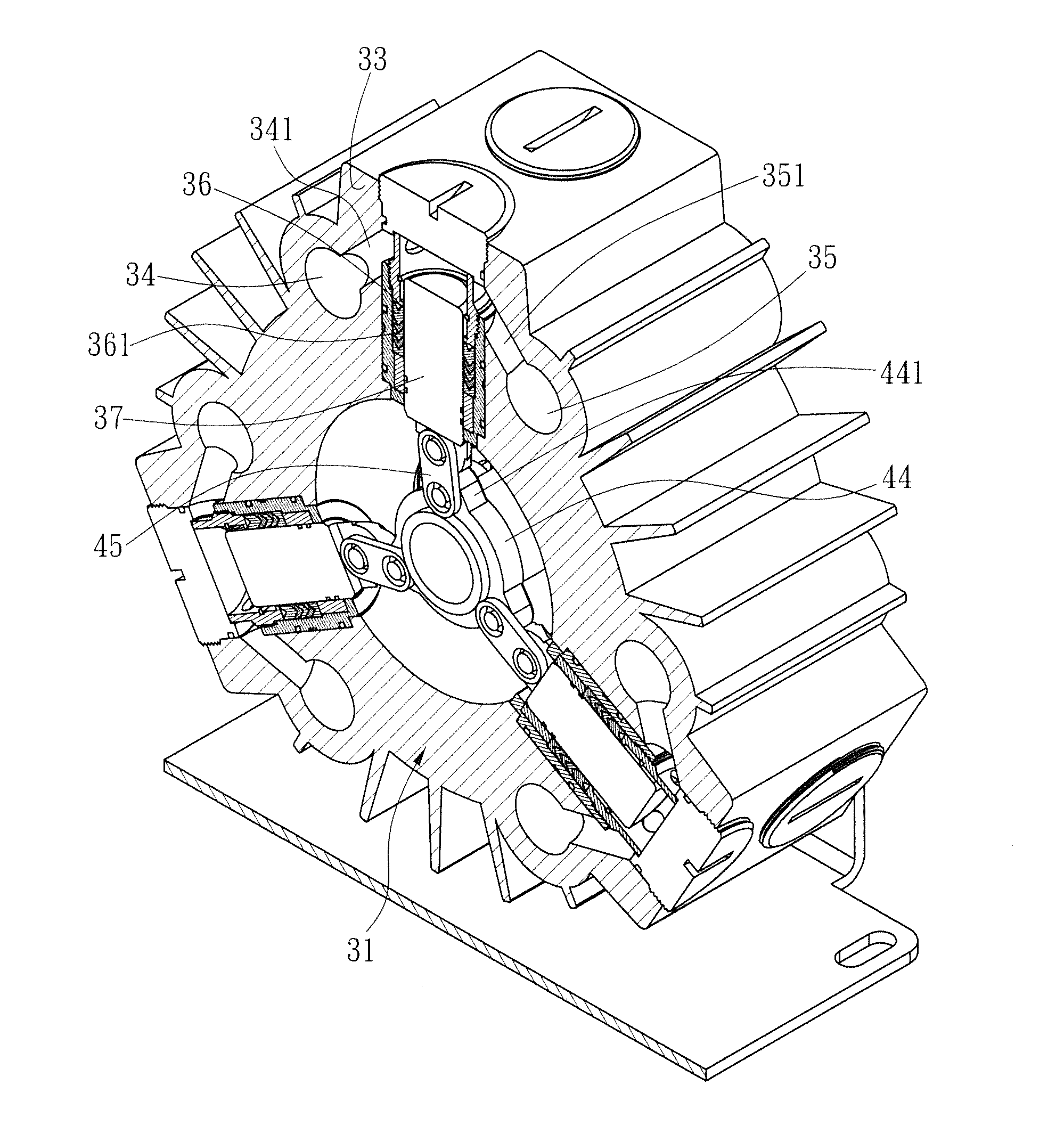
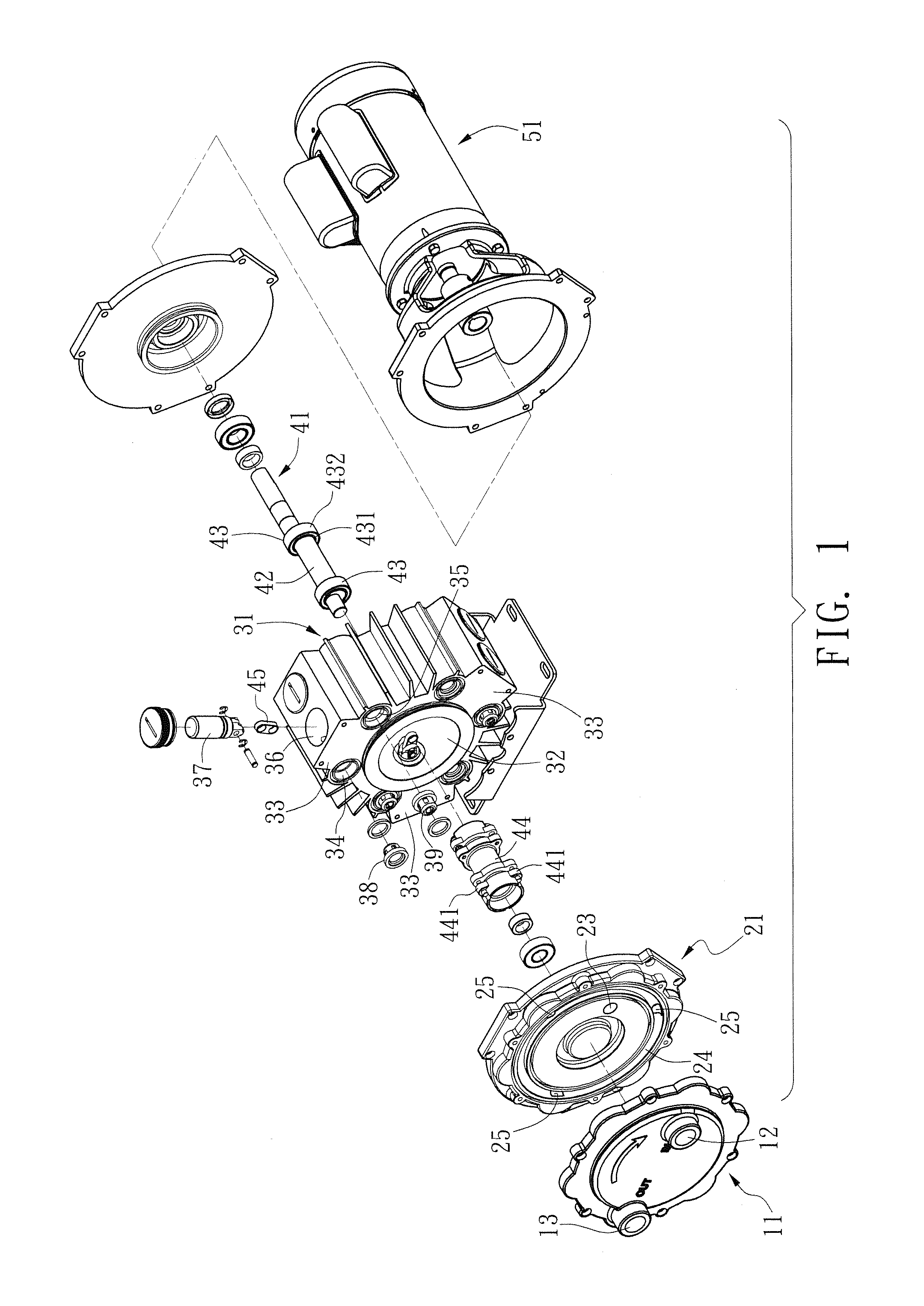
[0022]Please refer to FIGS. 1 to 4. The disclosed structure of a pressurizing pump consists mainly of a cover 11, a flow guide 21, a pump 31, and a main axle 41.

[0023]The cover 11 has an inlet 12 and an outlet 13. The flow guide 21 is interposed between the cover 11 and the pump 31.

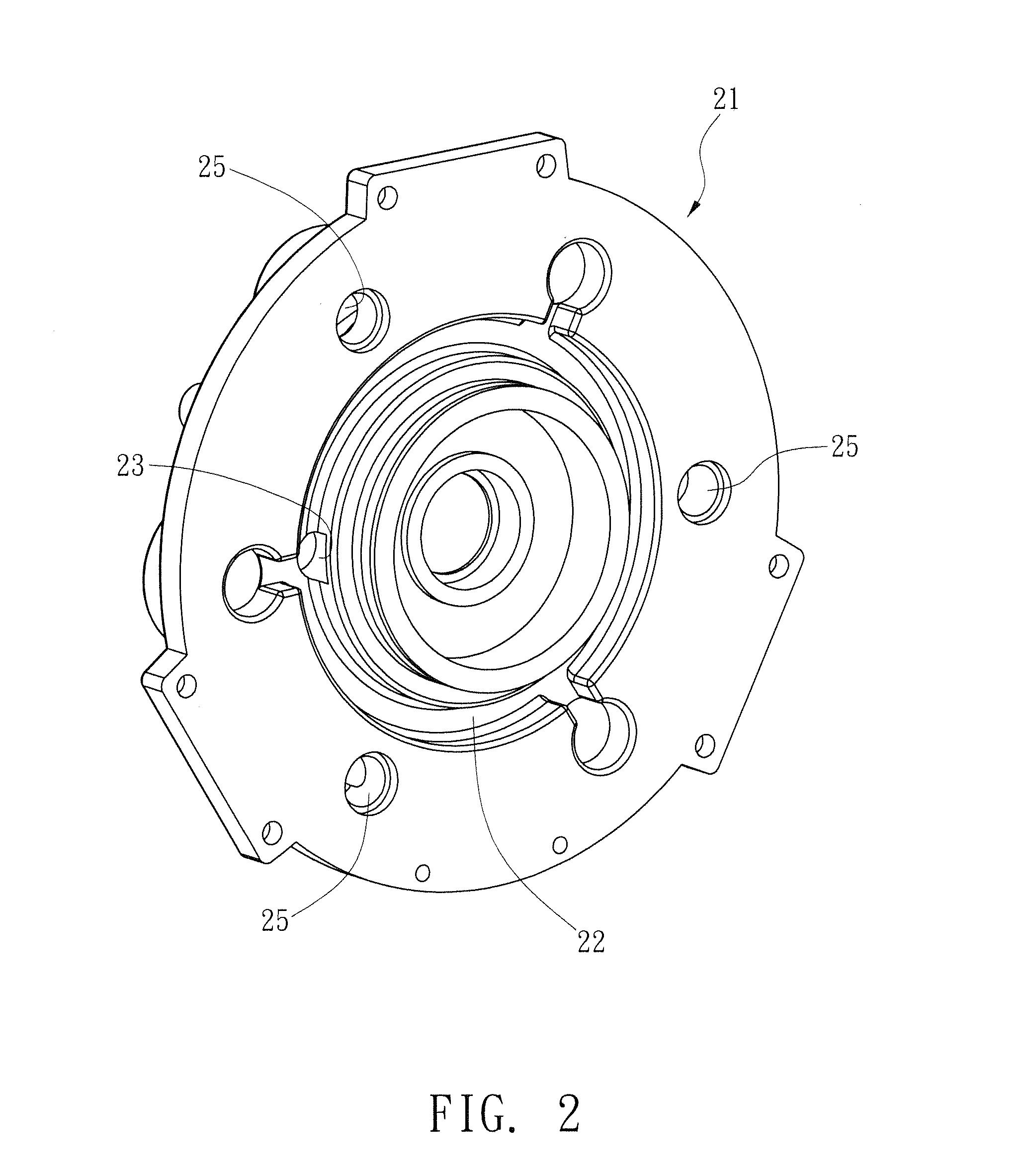
[0024]The flow guide 21 has a disk shape. The side of the glow guide 21 facing the pump 31 is annually formed with a first passage 22. The flow guide 21 is formed with a first connecting hole 23 via which the first passage 22 is connected with the inlet 12. The side of the flow guide 21 facing the cover 11 is annually formed with a second passage 24 connected with the outlet 13. The second passage 24 is formed with a second connecting hole 25 that at least goes through the flow guide 21.

[0025]The pump 31 is...


PUM


Abstract

A pressurizing pump structure includes a cover, a flow guide, a pump and a main axle. The flow guide is interposed between the cover and the pump. The main axle is mounted inside the pump. The pump has several pressurizing chambers, each of which has one or more pressurizing tanks. Each of the pressurizing tanks has a piston. The main axle has an eccentric part going into the pump for driving the pistons in the pressurizing tanks to make reciprocal motions as the main axle rotates, thereby outputting fluid with a higher pressure.

Description

BACKGROUND OF THE INVENTION[0001]1. Field of Invention[0002]The invention relates to a pump structure and, in particular, to a pressurizing pump structure that has a better structural strength and satisfies the high-pressure output demand.[0003]2. Related Art[0004]A conventional pressurizing pump structure is shown in FIG. 9. It mainly consists of a driving part 91 and a pump cover 92. The top of the driving part 91 is protruded with several equally spaced driving rods 93. The top of each of the driving rods 93 is locked with a top chip 94. The bottom of the driving part 91 is provided with a bearing 95 connected with a driving head 96. The bottom of the driving head 96 is further connected with the output axle of a motor 97. The driving head 96 and the output axle of the motor 97 are disposed eccentrically. When the motor 97 rotates the driving head 96, the driving head 96 sequentially drives the top chips 94 on the driving rods 93 to perform a reciprocal motion by moving up and do...

Claims


Application Information

Patent Timeline
IPC IPC(8): F04B41/06
CPCF04B53/162F04B9/045
Inventor TENG, MIN-CHIENTENG, PO-SHENG
Owner TENG MIN CHIEN
Why Eureka
Eureka Blog
Learn More