Method for designing a bone morphology based hip system

a hip system and hip technology, applied in the field of hip system design, can solve the problems of typical implant system growth not accurately reflecting the geometries of different bone sizes, inability to develop a new hip system design, and inability to use bone morphology data for new implant designs, etc., to achieve the effect of improving the shape of the hip stem design

Active Publication Date: 2013-08-01
HOWMEDICA OSTEONICS CORP
View PDF0 Cites 16 Cited by
  • Summary
  • Abstract
  • Description
  • Claims
  • Application Information

AI Technical Summary

Problems solved by technology

However, a method to utilize bone morphology data for new implant designs has not been developed.
Typical implant system growth does not accurately reflect the geometries of different bone sizes.
Thus, implant sets made in accordance with traditional methodologies may, in some cases, fit poorly when installed, and may lead to implant failure for the reasons discussed above or for other reasons.

Method used


Image

  • Method for designing a bone morphology based hip system
  • Method for designing a bone morphology based hip system
  • Method for designing a bone morphology based hip system

Examples


example

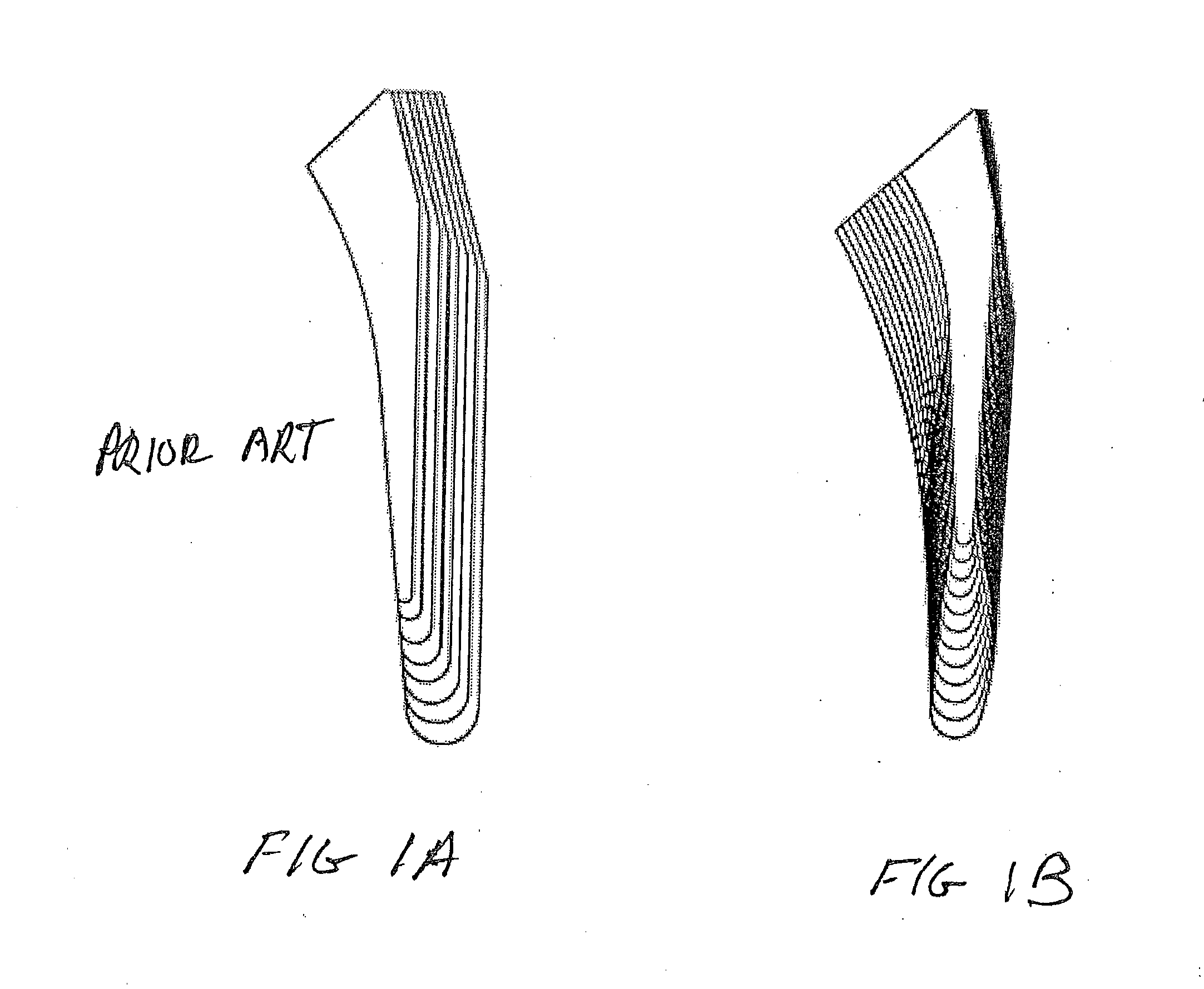
[0077]Five stems of the prior art (STD) tapered wedge design similar to FIG. 1 (Accolade® TMZF, Stryker Orthopaedics, Mahwah, N.J.) and the stem of the present invention were implanted into a homogenous set of 10 synthetic femora utilizing large left fourth generation composite femurs (purchased from Sawbones, Pacific Labs, Seattle, Wash.).

[0078]The six-degrees-of-freedom (6 DoF) motions of the implanted stems were recorded under short-cycle stair-climbing loads similar to a previous study of press-fit stems.

[0079]Minimum head load was 0.15 kN and the maximum varied between 3 Body Weights (BW) and 6 BW. Loading began with 100-cycles of 3 BW and was stepped up to 4 BW, 5 BW and 6 BW for 50-cycles each. Prior to each load increase, 50 cycles of 3 BW loading was applied. This strategy allowed a repeatable measure of cyclic stability after each higher load was applied.

[0080]The 6 DoF micromotion data, acquired during the repeated 3 BW loading segments, were reduced to four outcome measu...


PUM


Abstract

A method of designing a group of femoral implants from three-dimensional images of femurs from a patient population greater than 100. A boundary between cortical and cancellous bone is defined in each of the images. A longitudinal axis of the femur is defined centered within the boundary. The width of the boundary is measured in a direction perpendicular to the axis at multiple cross-sections along the longitudinal axis spaced less than 20 mm. At least five (5) different size implants for implantation in a noncortical bone area of the femur are designed based on the measured widths. At least one area of the proximal femoral component boundary is designed where the implant outer surface is sized to be within 2 mm of the cortical bone. The proximal dimensions of the at least five implants are sized to provide the fit within 2 mm in 95% of the femurs from the population.

Description

BACKGROUND OF THE INVENTION[0001]This invention relates to a method of using bone morphology data to design a family of prosthetic hip implants.[0002]The femoral fit of a prosthetic hip stem component is a key factor for the long term success of a cementless total hip replacement. Traditionally, hip stems have been designed based on predicate clinical data and limited bone morphology data. Numerous studies have analyzed the femur bone morphology. For example, (1) Noble et al., Clinical Orthopaedics and Related Research, 1988; (2) Husmann et al., Journal of Arthoplasty, 1997; (3) Laine et al., Journal of Arthoplasty, 2000; (4) Dorr et al., Bone, 1993; (5) Khang et al., Clinical Orthopaedics and Related Research, 2003; (6) Bo et al., Journal of Orthopaedic Science, 1997. However, a method to utilize bone morphology data for new implant designs has not been developed.[0003]Because bone geometries vary from person to person (and may also vary with age), typical orthopeadic implants are ...

Claims


Application Information

Patent Timeline
Patent Type & Authority Applications(United States)
IPC IPC(8): G06F17/50
CPCA61F2/3662A61F2002/30616A61F2/3859A61B5/4528A61B17/155A61F2/3094
Inventor WUESTEMANN, THIESBASTIAN, ADAM
Owner HOWMEDICA OSTEONICS CORP
Why Eureka
Try Eureka