
Icing protection system for an aircraft and method for operating an icing protection system

a protection system and aircraft technology, applied in the direction of defrosting, domestic cooling apparatus, application, etc., can solve the problems of heat transfer, in-flight use, and realization of the aircraft's internal wing deicing system

Active Publication Date: 2013-08-08
AIRBUS OPERATIONS GMBH
View PDF1 Cites 18 Cited by
  • Summary
  • Abstract
  • Description
  • Claims
  • Application Information

AI Technical Summary

Benefits of technology

The invention proposes an effective and low fuel consumptionicing protection system for aircraft that increases the range of the aircraft compared to conventional systems. The system uses a thermal deicing device to control the surface temperature of the aircraft to 60 °C, allowing water to evaporate completely. This prevents the water from refreezing and accumulating into ice formations. The system is based on condensation and provides a high heat flow to thaw ice and achieve a complete evaporation of the thaw water within the operating range of the aircraft.

Problems solved by technology

Due to the high energy content of the hot bleed air obtained from the main engines, an internal wing deicing system of an aircraft realized in accordance with the prior art can only be utilized in-flight because material overheating of the wing structure may easily occur on the ground due to the lack of relative wind.
Despite the high energy content of the bleed air obtained, for example, from main engines, the heat transfer is limited by the comparatively low heat transfer coefficient of air such that the deicing still cannot always be precisely controlled and is predominantly ensured by excess bleed air.

Method used


Image

  • Icing protection system for an aircraft and method for operating an icing protection system
  • Icing protection system for an aircraft and method for operating an icing protection system
  • Icing protection system for an aircraft and method for operating an icing protection system

Examples


Embodiment Construction

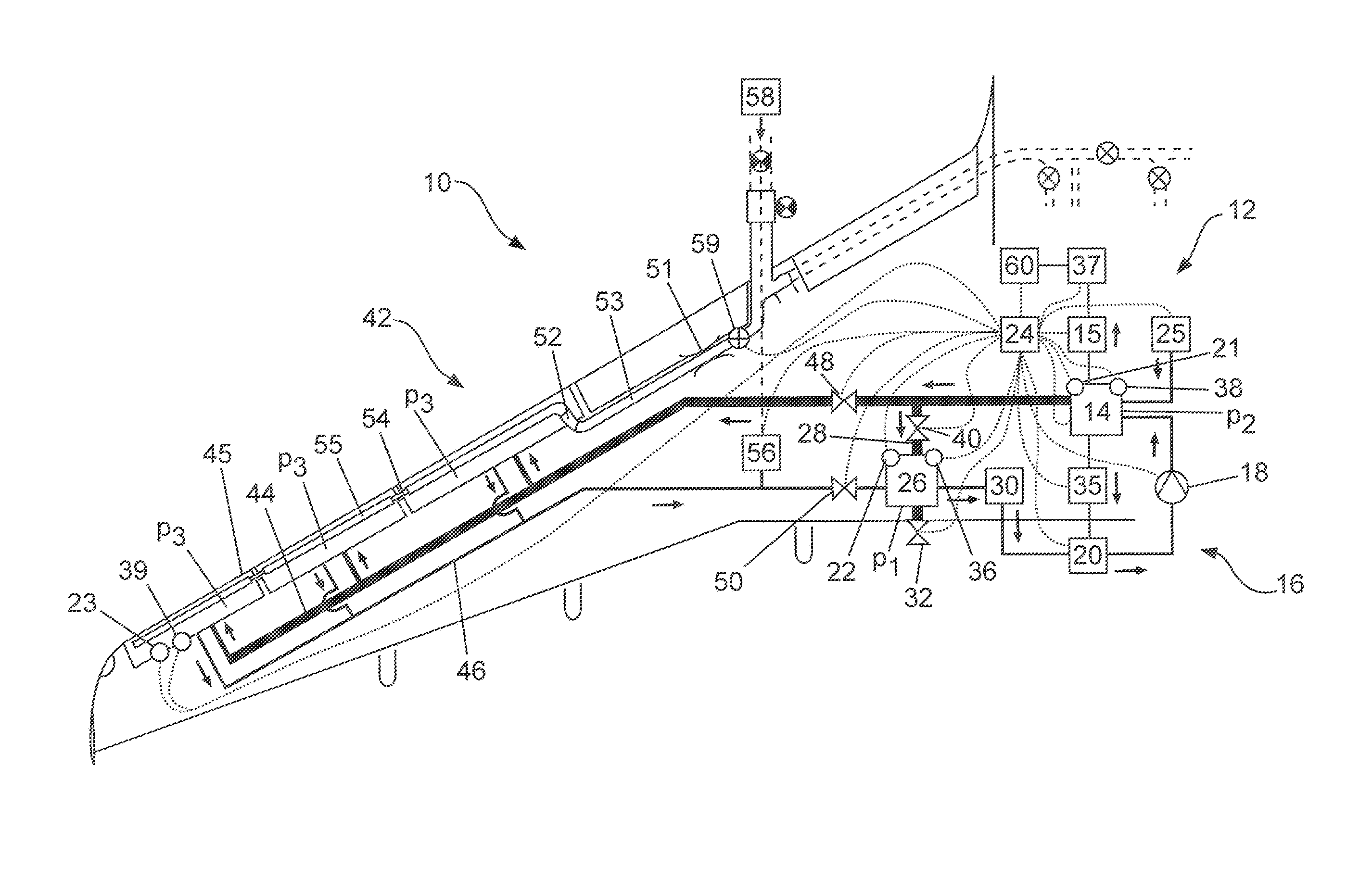
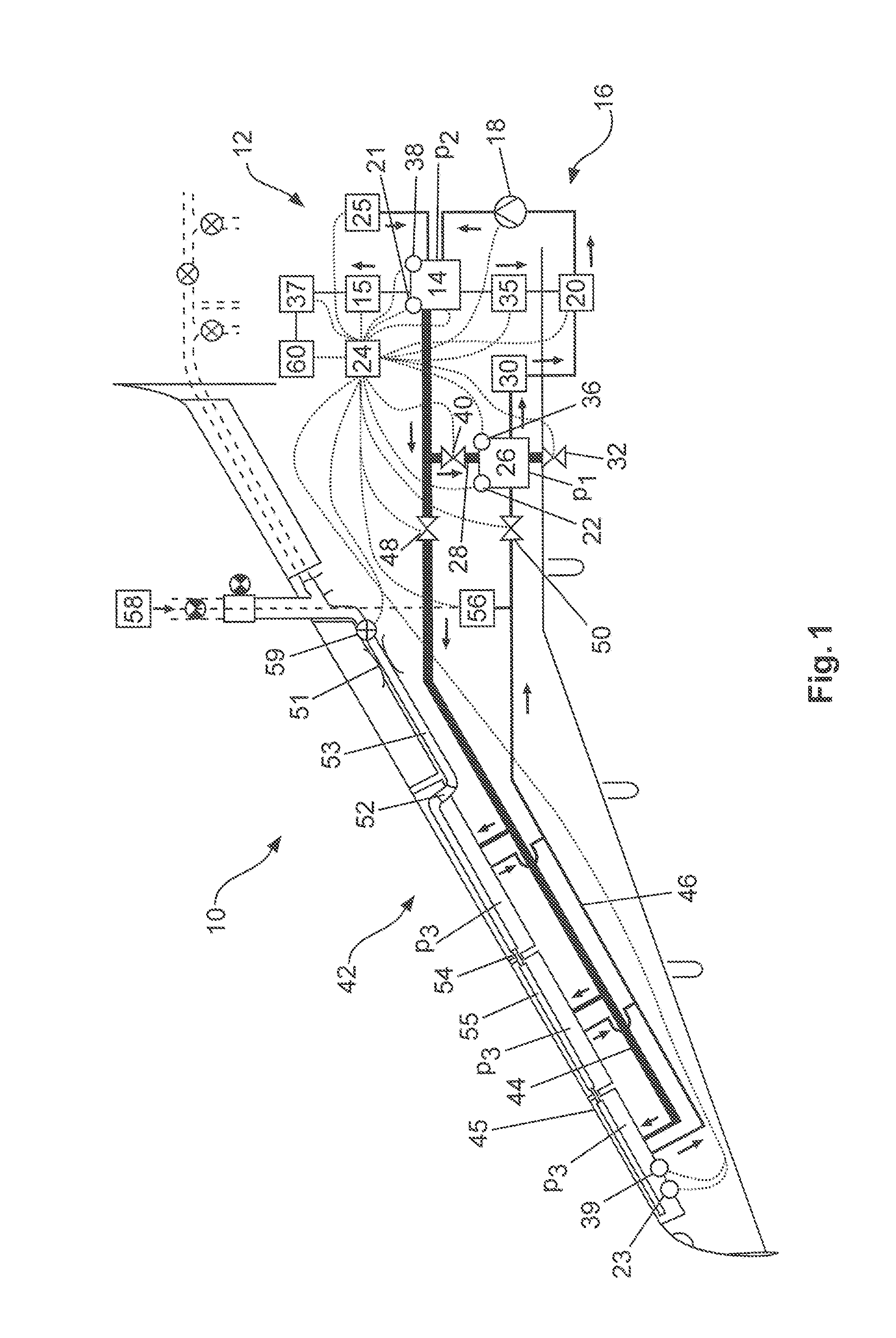
[0054]FIG. 1 shows an icing protection system 10 according to the invention in an aircraft. It contains an evaporatively cooled fuel cell system 12 that is preferably arranged in a non-pressurized region of the aircraft such as, for example, in a fairing of a wing-fuselage transition (also referred to as “belly fairing”). The fuel cell system 12 comprises a fuel cell 14 that is realized in the form of a fuel cell stack in the described example. The fuel cell 14 may be realized in the form of a low-temperature PEM fuel cell with an operating temperature range between 60° C. and 110° C., as well as in the form of a high-temperature PEM fuel cell with operating temperatures in excess of 200° C.

[0055]The evaporatively cooled fuel cell system 12 contains a fuel cell 14 and an evaporative cooling system 16 that is in thermal contact with the fuel cell 14 in order to absorb and remove from the fuel cell 14 heat generated by the fuel cell 14 during the operation of the fuel cell 14 by evapo...


PUM


Abstract

An icing protection system comprises a fuel cell, an evaporative cooling system, a thermal deicing device, a control unit and a device for measuring the pressure in the evaporative cooling system. The evaporative cooling system is in thermal contact with the fuel cell and with the thermal deicing device in order to conduct heat from the fuel cell to the thermal deicing device. The control unit controls the electrical power demanded from the evaporatively cooled fuel cell in dependence on a deviation of the pressure measured by the pressure measuring device from a predetermined NOMINAL pressure. In this way, an energetically very efficient and very well controllable icing protection system is made available that can be operated without bleed air supplied by engines or electrical energy provided by engine generators.

Description

REFERENCE TO RELATED APPLICATIONS[0001]This application claims the benefit of the filing date of German Patent Application No. 10 2012 002 132.1 filed Feb. 3, 2012 and of U.S. Provisional Patent Application No. 61 / 594,549 filed Feb. 3, 2012, the disclosure of which applications is hereby incorporated herein by reference.TECHNICAL FIELD[0002]The invention pertains to an icing protection system for an aircraft and a method for operating an icing protection system of an aircraft.BACKGROUND OF THE INVENTION[0003]It is known to carry out the deicing of surfaces prone to icing with the aid of heated air that originates, for example, from main engines or from an auxiliary power unit (Auxiliary Power Unit, APU) and is usually routed through a deicing valve, a throttling element and a piccolo tube that is respectively situated in the interior of the wing nose or slats (slats). The hot engine bleed air escapes through the openings of the piccolo tube and flows directly along an underside or i...

Claims


Application Information

Patent Timeline
Patent Type & Authority Applications(United States)
IPC IPC(8): F25D21/04
CPCF25D21/04B64D15/02Y02T90/36B64D15/06B64D2041/005B64D15/04Y02T90/40Y02E60/50H01M8/04059
Inventor SCHEIBERT, TOBIAS
Owner AIRBUS OPERATIONS GMBH
Learn More