Leakage inspection apparatus and leakage inspection method

a leakage inspection and leakage inspection technology, applied in the direction of measurement devices, structural/machine measurement, instruments, etc., can solve the problems of increasing the cost of the apparatus, unable to handle the method, and unable to inspect the leakage minutely,

Active Publication Date: 2013-08-08
YAMAGUCHI UNIV +1
View PDF5 Cites 11 Cited by
  • Summary
  • Abstract
  • Description
  • Claims
  • Application Information

AI Technical Summary

Benefits of technology

[0024]According to the leakage inspection apparatus and the leakage inspection method according to the present invention in which a liquid is used as a probe medium, a probe liquid of a high pressure is supplied to the inside of the tested body which is in a sealed state and disposed in the tested body chamber which is evacuated and the concentration of the probe medium having leaked and ha...

Problems solved by technology

Therefore, establishment of a method for inspecting a minute leakage also serving as a high pressure tightness inspection has been an urgent problem.
This causes a considerable apparatus cost increase in comparison with the conventional apparatus an...

Method used


Image

  • Leakage inspection apparatus and leakage inspection method
  • Leakage inspection apparatus and leakage inspection method
  • Leakage inspection apparatus and leakage inspection method

Examples


working example 1

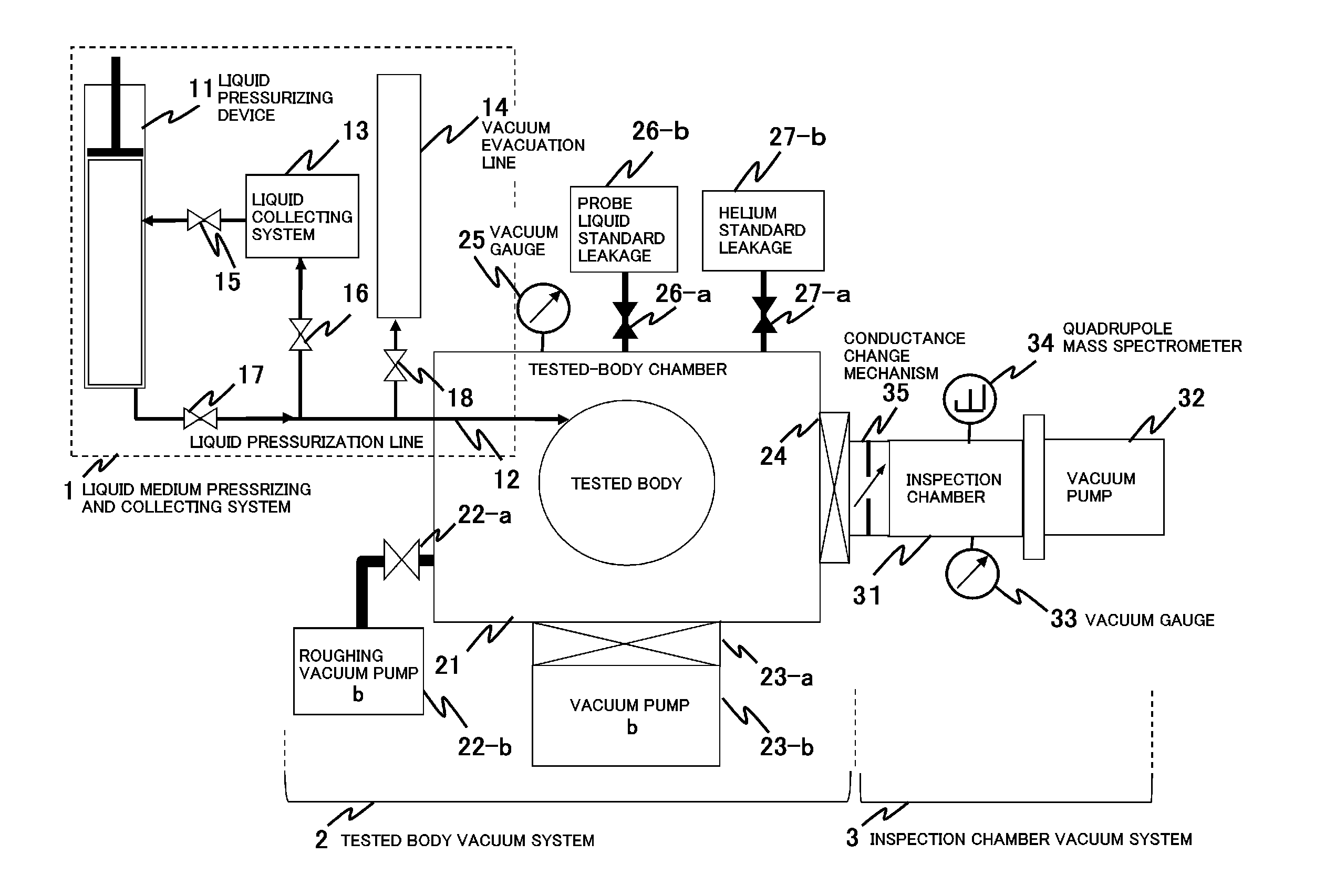
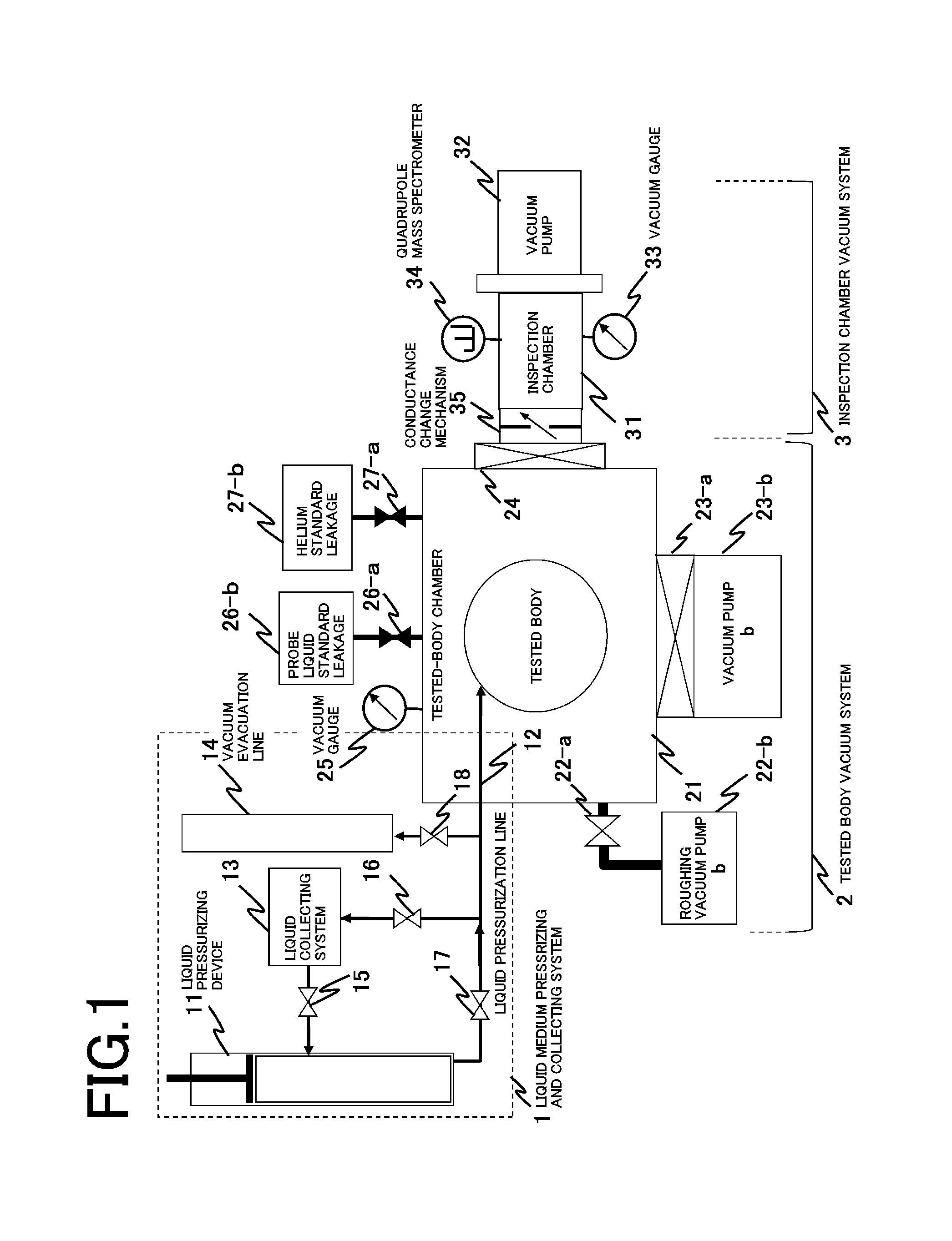
[0109]Methanol was selected as the probe liquid in the working example 1 according to the present invention and leakage inspection was performed by using the high pressure liquid leakage inspection apparatus as shown in FIG. 1 and compared with a helium leakage inspection method according to a conventional helium leak test.

[0110]Herein, a pressurizing device capable of applying pressure up to the maximum 200 MPa was used for pressurizing liquid. A stainless-steel vacuum chamber having a size of φ200 mm×300 mm and subjected to precision chemical polishing treatment was used for the tested-body chamber 21, an oil-sealed rotary pump having a pumping speed of 1.7×10⁻² m3s−1 was used for the roughing vacuum pump 22-b and connected to the tested-body chamber via the vacuum valve 22-a and a turbo-molecular pump having a pumping speed of 1.0 m3s−1 is used for the vacuum pump 23-b and connected to the tested-body chamber via the vacuum valve 23-a.

[0111]A stainless-steel vacuum chamber of φ ...

working example 2

[0127]A liquid medium in which a probe gas having small activation energy for desorption is dissolved may be used as a method for avoiding the problem that it takes a lot of time for the next inspection due to remaining probe liquid after a large amount of leakage is generated by the inspection. The liquid medium in which a probe gas is dissolved includes carbonic acid water, hydrogen peroxide water, ammonia water, etc. Hereinafter, an example of the case where carbonic acid water was used as the liquid medium in which a probe gas is dissolved will be described.

[0128]Considering that the solubility of carbon dioxide in water at normal temperature (25° C.) under one atmospheric pressure is 3.9×10⁻² molL−1 which is a low value, carbonic acid water, as a liquid medium in which a probe gas is dissolved, was prepared in which carbon dioxide was dissolved in water under a high pressure of 0.7 MPa and which has a concentration of 2.73×10⁻¹ molL−1, in order to facilitate the inspection usin...


PUM


Abstract

Provided are a leakage inspection apparatus and a leakage inspection method for inspecting the flow rate of leakage from a tested body disposed in a tested-body chamber 21. The leakage inspection apparatus includes liquid supplying and pressurizing means 11 for supplying a probe liquid to the inside of the tested-body chamber 21 and pressurizing the probe liquid to a high pressure 0.1 MPa or more, vacuum evacuation means 22-b, 23-b and a quadrupole mass spectrometer 34. The tested body 21 is evacuated, the probe liquid is supplied to the inside of the tested body and pressurized to 0.1 MPa or more and the concentration of a probe medium leaked from the tested body and evaporated in a vacuum is measured by the quadrupole mass spectrometer 34, thereby measuring the flow rate of leakage from the tested body. This makes it possible to determine the flow rate of leakage using a liquid as a probe medium and simultaneously possible to perform a pressure tightness inspection at an atmospheric pressure of 0.1 MPa or more, especially at a high pressure ranging from 1 MPa to 1 GPa.

Description

FIELD OF THE INVENTION[0001]The present invention relates to a leakage inspection apparatus and leakage inspection method applied for various kinds of consumer and industrial parts such as automotive parts, aircraft parts, etc. and packages. The apparatus and the method are provided to quantitatively inspect leakage caused in the structures, per se, of the above items, defects of joint portions or seal portions formed by welding, etc.BACKGROUND OF THE INVENTION[0002]For various pants of automobiles and airplanes, various parts structuring gas facilities or water facilities and packages for foods, medical products, etc., it is necessary to inspect leakage caused in the structures, per se, of these items and defects of joint portions and seal portions formed by welding, etc., thereof. Leakage inspection methods have been used, which are illustrated in Table 1, that is, “pressorization foaming method”, “in-water foaming method”, “color check method”, “ultrasonic method”, “differential ...

Claims


Application Information

Patent Timeline
IPC IPC(8): G01M3/20
CPCG01M3/229G01M3/3281G01M3/20
Inventor YAMAMOTO, SETSUOKURISU, HIROKITAKADA, NAOKINAKAGAWA, MITSUGUTSUGE, KATSUSHIISHIKAWA, YUKIHIRO
Owner YAMAGUCHI UNIV
Why Eureka
Try Eureka