System and method for transferring natural gas for utilization as a fuel

a technology of natural gas and fuel, applied in the direction of liquid transferring device, service pipe system, packaging, etc., can solve the problems of leaking inert gas in the jacket space, little to no natural gas fuel is released to the atmosphere, and the pressure in the jacket space is reduced

Inactive Publication Date: 2013-08-08
ARGENT MARINE MANAGEMENT
View PDF4 Cites 19 Cited by
  • Summary
  • Abstract
  • Description
  • Claims
  • Application Information

AI Technical Summary

Benefits of technology

[0017]It has now been found that the foregoing problems are solved in the form of several separate, but related, aspects. A flexible gas transfer assembly is connected using connectors that incorporate self-closing valves in both halves of the connectors, so that natural gas fuel is contained within the gas transfer assembly when the assembly is disconnected, thereby eliminating the need to purge the gas transfer assembly with inert gas prior to disconnecting it. Additionally, little to no natural gas fuel is released to the atmosphere due to the self-sealing nature of the connectors.

Problems solved by technology

Additionally, little to no natural gas fuel is released to the atmosphere due to the self-sealing nature of the connectors.
If the inner transfer hose develops a leak, the higher pressure inert gas in the jacket space will leak into the inner transfer hose that carries the natural gas fuel.
Likewise, a leak in the outer jacket will cause the inert gas to leak out, thereby causing a drop in the pressure in the jacket space and also causing a system shutdown.
In this manner, any failure of the gas transfer assembly will result in the flow of natural gas fuel being shut down automatically.
Another potential source of natural gas leakage is the connectors, both the normal quick connect / disconnect connectors and the emergency breakaway connectors, that are used to couple the gas transfer assembly to the tugboat and to the barge.
Even minor leakages of natural gas that would be undetectable by other means will be detected by the gas detectors and will cause alarms and system shutdowns.

Method used


Image

  • System and method for transferring natural gas for utilization as a fuel
  • System and method for transferring natural gas for utilization as a fuel
  • System and method for transferring natural gas for utilization as a fuel

Examples


Embodiment Construction

[0034]Definitions of certain terms used in this specification are as follows:

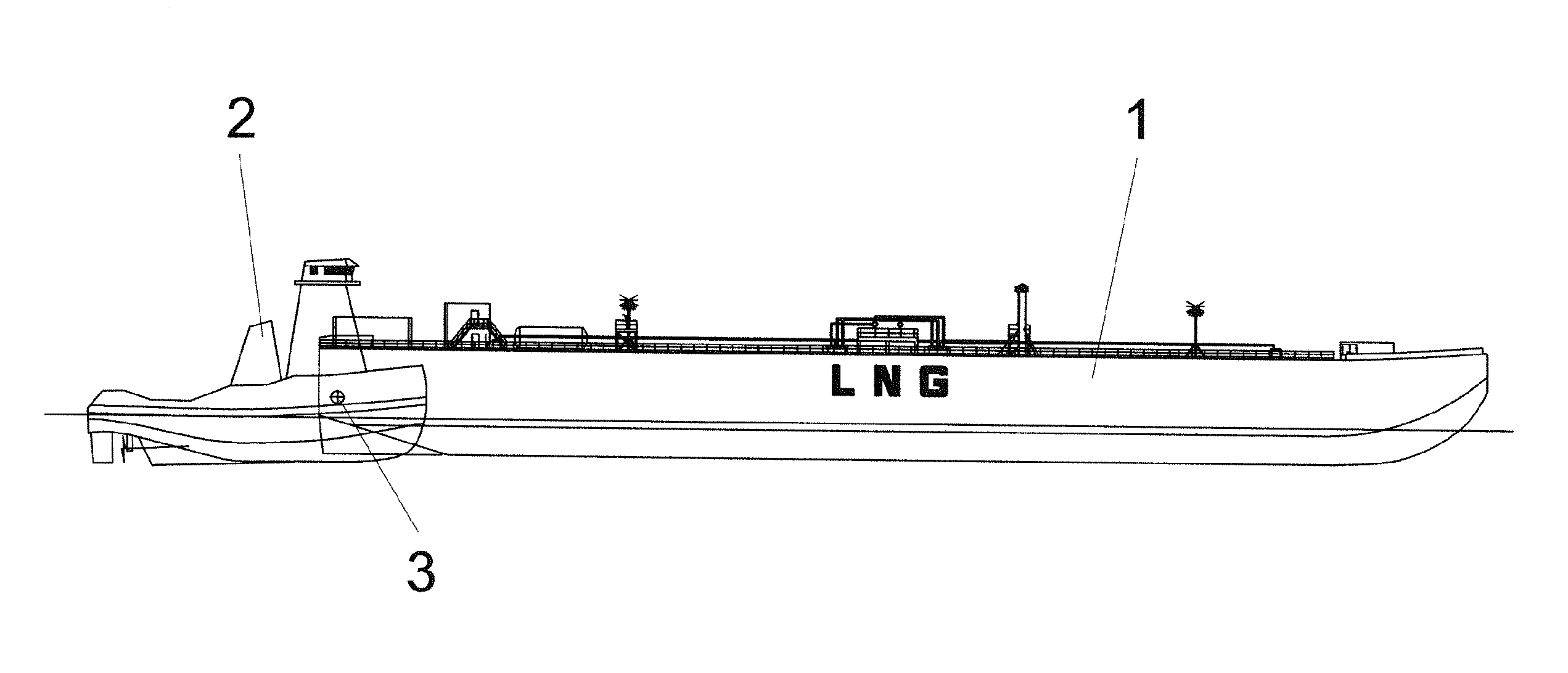
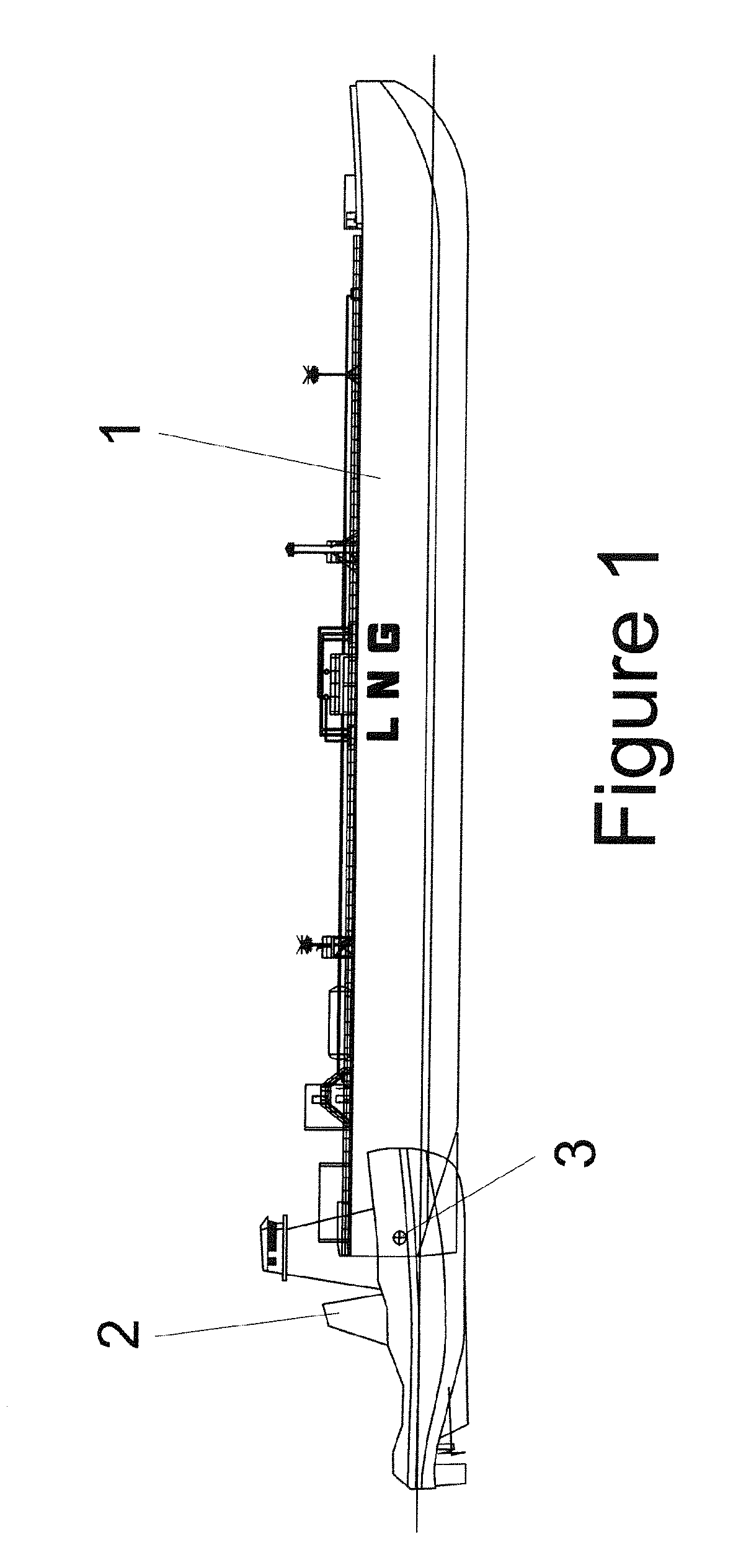
[0035]Vehicle—any means in or by which something is carried or conveyed; a means of conveyance or transport. As used herein, the term “vehicle” includes but is not limited to marine vessels (e.g., ships, tugboats, towboats, barges, and articulated tug / barges (“AT / Bs”)) and land vehicles (e.g., railroad locomotives, railroad cars, and trucks).

[0036]Self-propelled vessel—a marine vessel that possesses permanently installed capability to propel itself at sea, i.e., a “ship.”

[0037]Non-self-propelled vessel—a marine vessel that is without a permanently installed capability to propel itself at sea, i.e., a “barge.” A “self-propelled” vessel that, for whatever reason, is not using its installed capability for propulsion is not, as defined herein, a “non-self-propelled” vessel.

[0038]LNG—liquefied natural gas.

[0039]LNGC—a self-propelled LNG carrier of ship form.

[0040]LNG Barge—a non-self-propelled LNG carrier.

[0041]...


PUM


Abstract

Natural gas is produced when LNG that is contained in an insulated LNG cargo tank(s) of a non-self-propelled LNG carrier (i.e., a barge) evaporates as a result of heat leakage through the walls of the insulated cargo tank(s). The natural gas is transferred from the barge to a tugboat or a towboat that is equipped with natural gas burning engines through a flexible gas transfer assembly so that the tugboat is powered by the natural gas fuel. The pressure in the cargo tank(s) on the barge is, therefore, effectively managed to prevent or substantially reduce the buildup of pressure within the LNG cargo tank(s). The LNG can then be contained within the LNG cargo tank(s) for an appropriate period of time and can be delivered at an appropriate and acceptable equilibrium pressure and temperature.

Description

FIELD OF THE INVENTION[0001]The present invention generally relates to the transportation of a cryogenic liquid such as LNG. More particularly, the present invention relates to a system and a method by which a gas provided by the evaporation of a portion of the cryogenic liquid is transferred, in a sound operating manner and in compliance with all governing international regulations, from the storage tank(s) of a land or marine vehicle for the purpose of being used as fuel by the gas-burning engines of the another land or marine vehicle.BACKGROUND OF THE INVENTION[0002]Natural gas, when cooled to approximately −260° F., changes phase from a gas to a liquid, thus “Liquefied Natural Gas” or “LNG.” In this phase change process, the volume required to hold a specific quantity of natural gas is reduced by approximately 600 times, thus making it possible to transport significant, and economic quantities of natural gas over great distances from source to market.[0003]LNG is a boiling cryog...

Claims


Application Information

Patent Timeline
Patent Type & Authority Applications(United States)
IPC IPC(8): F15D1/00
CPCF16L55/1015F16L2201/30B60K15/013Y02T70/90B63J2099/003Y02T70/34Y02T70/5263B63B27/34Y10T137/0318Y10T137/8326Y02T70/00Y02T70/50B67D9/00B67D7/3218F16K17/14
Inventor VAN TASSEL, GARY W.
Owner ARGENT MARINE MANAGEMENT
Why Eureka
Try Eureka