Light projection device and light guide member used in same

a technology of light projection device and light guide member, which is applied in the direction of lighting and heating apparatus, instruments, transportation and packaging, etc., can solve the problems of reducing the efficiency of light utilization, and achieve the effect of easy operation, easy and individual control of excitation states

Active Publication Date: 2013-08-08
SHARP FUKUYAMA LASER CO LTD
View PDF3 Cites 32 Cited by
  • Summary
  • Abstract
  • Description
  • Claims
  • Application Information

AI Technical Summary

Benefits of technology

[0012]In the light projection device of this invention, as described above, the excitation states of a plurality of application regions of the fluorescent member are individually controlled. In this way, it is possible to change the pattern of the light emitted from the fluorescent member, and thus it is possible to change the light projection pattern of the light emitted from the light projection device. Hence, since, in order to obtain a desired light projection pattern, it is not necessary to provide a light shielding plate that shields part of the fluorescent light, it is possible to reduce the decrease in the efficiency of utilization of the light. Moreover, since it is not necessary to provide the light projection device for each light projection pattern, it is possible to prevent the size of the light projection device as a whole from being increased.
[0034]Preferably, in the light projection device used as an automobile lighting unit, the light projection device is used as an automobile passing headlight and an automobile driving headlight. In this configuration, it is not necessary to separately provide a passing headlight and a driving headlight, and thus it is possible to prevent the size of the light projection device as a whole from being increased.

Problems solved by technology

Hence, since, in order to obtain a desired light projection pattern, it is not necessary to provide a light shielding plate that shields part of the fluorescent light, it is possible to reduce the decrease in the efficiency of utilization of the light.

Method used


Image

  • Light projection device and light guide member used in same
  • Light projection device and light guide member used in same
  • Light projection device and light guide member used in same

Examples


first embodiment

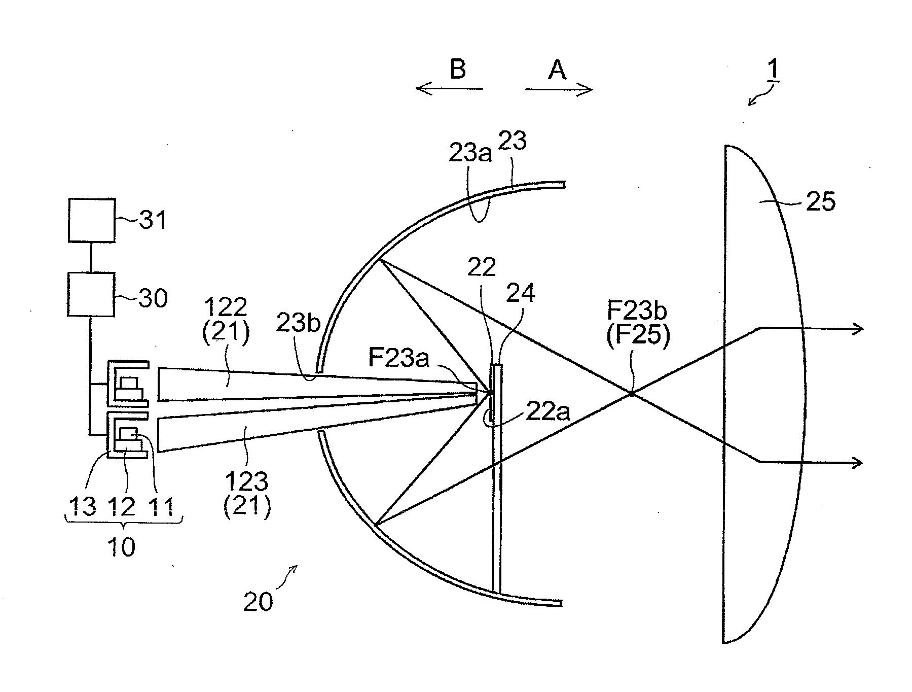
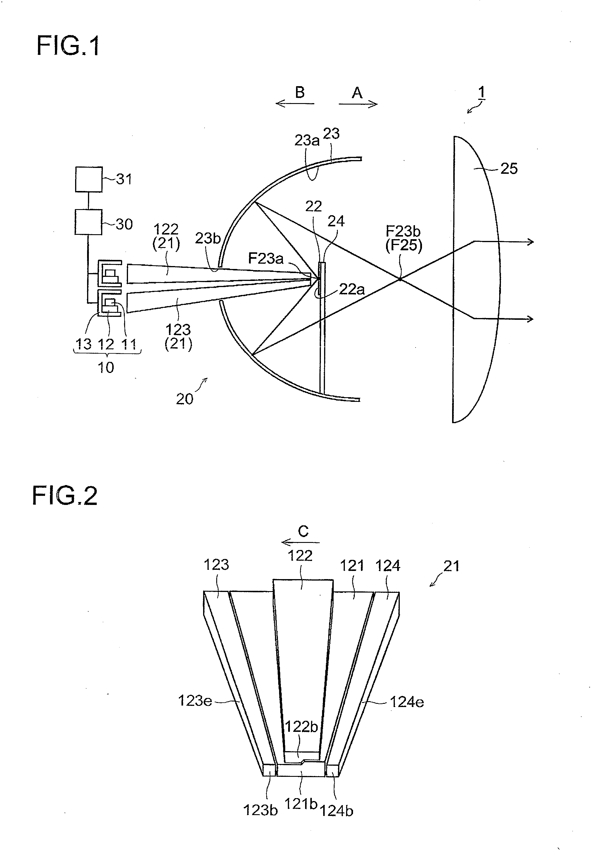
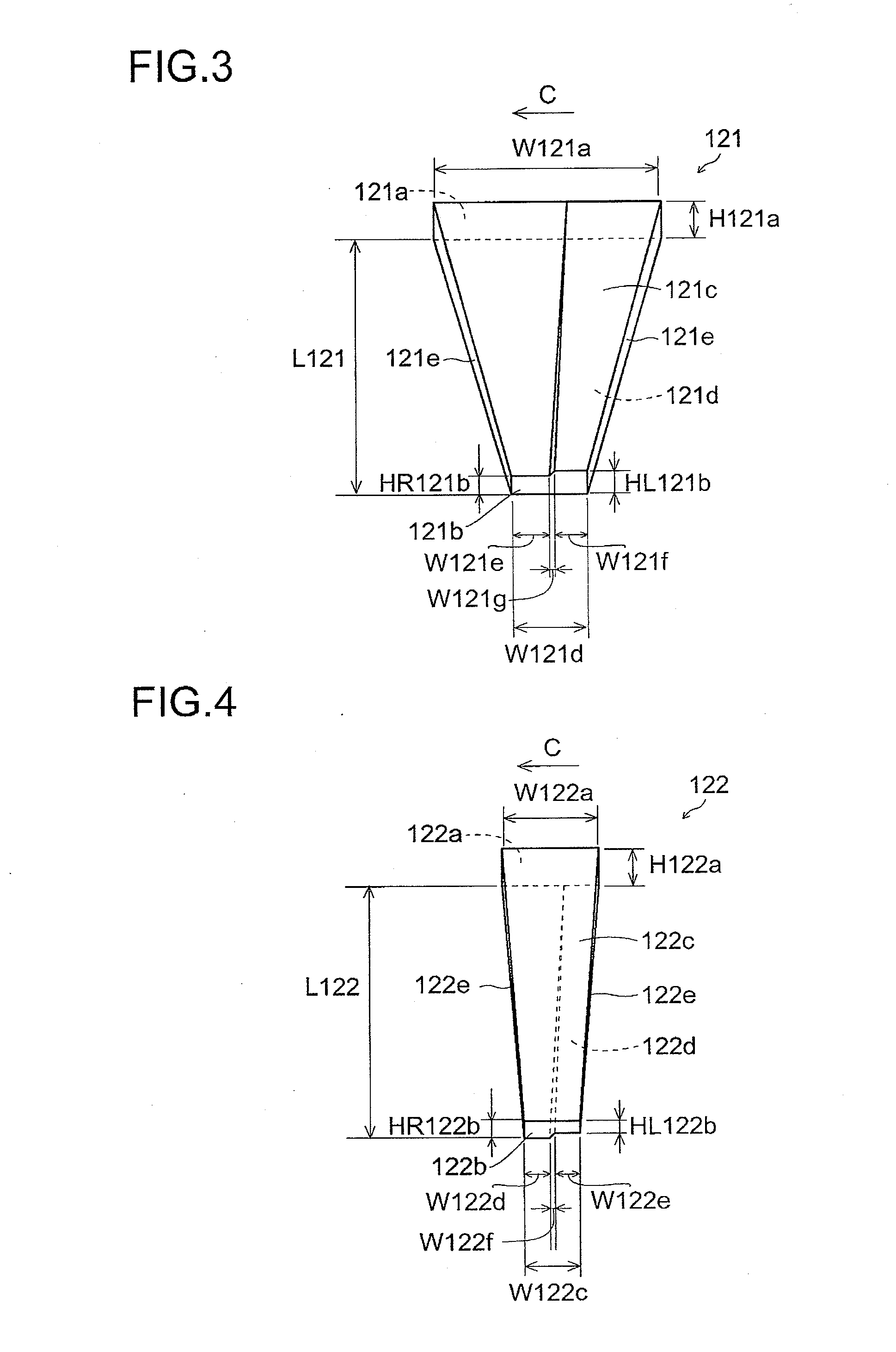
[0065]The structure of a light projection device 1 according to a first embodiment of the present invention will first be described with reference to FIGS. 1 to 11.

[0066]The light projection device 1 according to the first embodiment of the present invention is used as a headlight (lighting unit) that illuminates, for example, an area in front of an automobile (vehicle). As shown in FIG. 1, the light projection device 1 includes a plurality of laser generation devices 10 that function as a laser light source and a light projection unit 20 that utilizes laser light emitted from the laser generation devices 10 to project light in a predetermined direction (A direction).

[0067]The laser generation device 10 is a so-called CAN package semiconductor laser, and includes a semiconductor laser element (excitation light source) 11, a heat spreader 12 on which the semiconductor laser element 11 is mounted with solder or the like (not shown) and a metallic holding member 13 that holds these com...

second embodiment

[0124]In a second embodiment, unlike the first embodiment described above, a case where the light projection device functions as the headlight (lighting unit) and the blinker (lighting unit) will be described with reference to FIGS. 16 to 19.

[0125]In the light projection device according to the second embodiment of the present invention, as shown in FIG. 16, the light collection member 21 includes five light collection portions (light guide portions) 121 to 124 and 221. One laser generation device 10 is provided for the light collection portion 221. The output of the semiconductor laser element 11 corresponding to the light collection portion 221 is, for example, 0.3 W.

[0126]As shown in FIG. 17, the light collection portion 221 includes: a light entrance surface 221a through which the laser light emitted from the one semiconductor laser element 11 enters the light collection portion 221; a light emission surface 221b through which the laser light is emitted; and an upper surface 221...

third embodiment

[0139]In a third embodiment, unlike the first and second embodiments described above, a case where the light is projected by the reflective member 23 will be described with reference to FIG. 20.

[0140]In a light projection device 301 according to the third embodiment of the present invention, as shown in FIG. 20, a light projection unit 320 includes the light collection member 21, the fluorescent member 22, the reflective member 23 (light projection member) that reflects the fluorescent light emitted from the fluorescent member 22 in a predetermined direction (A direction), an attachment member 324 to which the fluorescent member 22 is fixed and a filter member 325 that is provided in the opening portion of the reflective member 23. In the light projection device 301, the lens 25 is not provided.

[0141]The application surface 22a of the fluorescent member 22 is inclined upward in the light projection direction (A direction). The back surface (the opposite surface to the application su...


PUM


Abstract

A light projection device that can change a light projection pattern is provided. The light projection device includes: a plurality of excitation light sources that emit excitation light; a fluorescent member that is excited by the excitation light from the excitation light sources; a control portion that controls outputs of the excitation light sources; and a light projection member that projects light emitted from the fluorescent member. The fluorescent member includes a plurality of application regions to which the excitation light is applied, and the control portion controls the outputs of the excitation light sources so as to individually control the excitation states of the application regions.

Description

[0001]This application is based on Japanese Patent Application No. 2012-024647 filed in Japan on Feb. 8, 2012, the contents of which are hereby incorporated by reference.BACKGROUND OF THE INVENTION[0002]1. Field of the Invention[0003]The present invention relates to a light projection device and a light guide member used in such a light projection device, and more particularly relates to a light projection device that includes a fluorescent member to which excitation light is applied and a light guide member used in such a light projection device.[0004]2. Description of the Related Art[0005]Conventionally, a light projection device is known that includes a fluorescent member to which excitation light is applied. Such a light projection device is disclosed in, for example, JP-A-2003-295319.[0006]JP-A-2003-295319 described above discloses a light source device (light projection device) that includes: an ultraviolet LD element functioning as a laser light source; a fluorescent material...

Claims


Application Information

Patent Timeline
Patent Type & Authority Applications(United States)
IPC IPC(8): B60Q1/04F21V13/12F21V9/16F21V9/40F21W107/10
CPCB60Q1/0047B60Q1/08B60Q1/34F21S48/1131F21S48/1747F21S48/215F21S48/1241F21S48/328B60Q1/04F21V9/16F21V13/12F21S48/1145F21S48/115F21S48/2293G03B21/204F21S41/125F21S41/141F21S41/24F21S41/663F21S43/14F21S43/251F21S45/47F21S41/16F21V9/30F21V9/08F21V13/14F21S41/176
Inventor TAKAHASHI, KOJI
Owner SHARP FUKUYAMA LASER CO LTD
Why Eureka
Try Eureka