Surface shape measurement method, surface shape measurement apparatus, non-transitory computer-readable storage medium, optical element, and method of manufacturing optical element

a technology of surface shape and measurement method, which is applied in the direction of reflective surface testing, instruments, computing, etc., can solve the problems of deteriorating the correction accuracy of the error generated by the relative movement between the object and the sensor, and achieve the effect of high accuracy

Active Publication Date: 2013-08-08
CANON KK
View PDF19 Cites 14 Cited by
  • Summary
  • Abstract
  • Description
  • Claims
  • Application Information

AI Technical Summary

Benefits of technology

[0007]The present invention provides a surface shape measurement method and a surface shape measurement apparatus that perform a stitching after correcting an error generated by a relative movement between an object and a sensor so as to be capable of measuring a surface shape of the object with high accuracy. In addition, the present invention provides a non-transitory computer-readable storage medium that stores the computer program for causing an information processing apparatus to execute the surface shape measurement method, an optical element that is manufactured by using the surface shape measurement method, and a method of manufacturing the optical element.

Problems solved by technology

In addition, a correction accuracy of the error generated by the relative movement between the object and the sensor is deteriorated.

Method used


Image

  • Surface shape measurement method, surface shape measurement apparatus, non-transitory computer-readable storage medium, optical element, and method of manufacturing optical element
  • Surface shape measurement method, surface shape measurement apparatus, non-transitory computer-readable storage medium, optical element, and method of manufacturing optical element
  • Surface shape measurement method, surface shape measurement apparatus, non-transitory computer-readable storage medium, optical element, and method of manufacturing optical element

Examples


embodiment 1

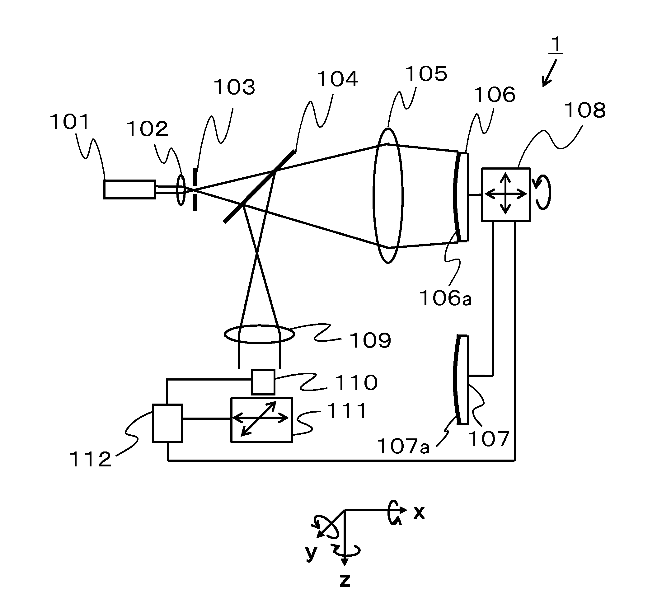
[0023]First of all, referring to FIG. 1, Embodiment 1 of the present invention will be described. FIG. 1 is a configuration diagram of a surface shape measurement apparatus 1 in the present embodiment. In FIG. 1, reference numeral 101 denotes a light source, reference numeral 102 denotes a condenser lens, reference numeral 103 denotes a pinhole, reference numeral 104 denotes a half mirror, and reference numeral 105 denotes a transmitter lens. Reference numeral 106 denotes a reference lens, and one of surfaces of the reference lens 106 is a reference surface 106a. Reference numeral 107 denotes a lens to be measured (an object to be measured), and one surface of the lens 107 is an object surface 107a (a surface to be measured). Reference numeral 108 denotes a driver that adjusts a position and an inclination of the reference lens 106 and the lens 107. Reference numeral 109 denotes an imaging lens, reference numeral 110 denotes a sensor, reference numeral 111 denotes a driver that driv...

embodiment 2

[0088]Next, referring to FIG. 5, Embodiment 2 of the present invention will be described. FIG. 5 is a flowchart of illustrating a method of making sensitivity in the present embodiment. The present embodiment is different from Embodiment 1 that makes the sensitivity by the calculation using the design value in that the sensitivity is measured and calculated in a measurement apparatus. In other words, the sensitivity of the present embodiment is calculated using a measured value that is obtained while the lens 107 and the sensor 110 are relatively moved. Other configurations are similar to those of Embodiment 1, and therefore descriptions of the configurations are omitted. Each step illustrated in FIG. 5 is, similarly to Embodiment 1, performed based on an instruction of the analyzing processor 112 of the measurement apparatus 1.

[0089]In FIG. 5, first of all, in Step S501, the reference lens 106 is set up and the alignment is performed. Subsequently, in Step S502, a division measurem...

embodiment 3

[0096]Next, referring to FIG. 6, Embodiment 3 of the present invention will be described. FIG. 6 is a flowchart of illustrating a method of making sensitivity in the present embodiment. The present embodiment performs division measurements of the wavefront slope distributions on the surface of the sensor 110 for the reference lens 106 and the lens 107 without performing a drive by a predetermined amount at a division measurement position so as to obtain data. Then, drive by the predetermined amount is given to the data in a computer so as to make the sensitivity. Thus, the present embodiment is different from Embodiment 1 or 2 in that the sensitivity is calculated by adding an error in the computer (an information processing apparatus). Other configurations are similar to those of Embodiment 1, and therefore descriptions of the configurations are omitted. Each step illustrated in FIG. 6 is, similarly to Embodiments 1 and 2, performed based on an instruction of the analyzing processo...


PUM


Abstract

A surface shape measurement method that divides a surface shape of an object (107) into a plurality of partial regions (201, 202, 203, 204) to obtain partial region data and that stitches the partial region data to measure the surface shape of the object, and the method includes the steps of calculating sensitivity of an error generated by a relative movement between the object and a sensor (110) for each of the partial regions, dividing the surface shape of the object into the plurality of partial regions to obtain the partial region data, obtaining the partial region data, calculating an amount corresponding to the error using the sensitivity, correcting the partial region data using the amount corresponding to the error, and stitching the corrected partial region data to calculate the surface shape of the object.

Description

BACKGROUND OF THE INVENTION[0001]1. Field of the Invention[0002]The present invention relates to a surface shape measurement method that divides a surface shape of an optical element so as to measure the surface shape.[0003]2. Description of the Related Art[0004]As a method of measuring a surface shape of an object surface (an optical element), particularly an aspherical lens, without contacting the surface at high speed, Jahannes Pfund, Norbert Lindlein and Johannes Schwider, “NonNull testing of rotationally symmetric aspheres: a systematic error assessment,” App. Opt. 40 (2001) p. 439 discloses a method of illuminating light of a spherical wave onto an object surface via an optical system to measure reflected light of the object surface using the Shack-Hartmann sensor of a light receiving unit. In a method of disclosing in Japanese Patent Laid-Open No. 2006-30016, in accordance with a diameter of the object or an aspherical surface amount (a deviation from the spherical surface), ...

Claims


Application Information

Patent Timeline
Patent Type & Authority Applications(United States)
IPC IPC(8): G06K9/50
CPCG01B11/255G01M11/005G06K9/50
Inventor YONETANI, YUKIFURUKAWA, YASUNORI
Owner CANON KK
Why Eureka
Try Eureka