Integrated microfluidic device for single oocyte trapping

a microfluidic device and oocyte technology, applied in the field of integrated microfluidic devices, can solve the problems of not only harming the oocyte, not suitable for simultaneous positioning of multiple oocytes, and inconvenient work, and achieve the effect of facilitating the further development of fertilized eggs

Active Publication Date: 2013-08-08
CAPITALBIO CORP +1
View PDF6 Cites 68 Cited by
  • Summary
  • Abstract
  • Description
  • Claims
  • Application Information

AI Technical Summary

Benefits of technology

[0010]Additionally, provided herein is a method for single oocyte trapping using the integrated microfluidic device disclosed above comprising: a) transporting oocytes by a liquid in the micro-channel, wherein said oocytes enter the micro-well array. In some embodiments, the method may further comprise: b) adding sperms to the micro-channel, wherein in vitro fertilization occurs in the micro-well array. In some embodiments, the method may further comprise: c) adding a new liquid to the micro-channel, wherein dead sperms and cell debris in said micro-channel are removed to facilitate further development of fertilized eggs. In some embodiments, the method may further comprise: d) retrieving fertilized eggs or embryos from the micro-well array.
[0011]In some embodiments, the microfluidic device may be placed in an incubator, e.g., a CO2 incubator. In some embodiments, the liquid in the micro-channel may be held still to allow sperms to swim to the micro-well array and enter the micro-wells. In some embodiments, the liquid in the micro-channel may be used to transport the sperms to the micro-well array. In some embodiments, the new liquid may be added by pipetting, and wherein the fluid in the micro-channel may be driven by the height difference between the ends of the micro-channel. In some embodiments, one end of the micro-channel may be connected with a syringe pump or similar device, and wherein the new liquid may be injected by positive or negative pressure. In some embodiments, the liquid stays still, or flows constantly or intermittently, during the embryo culture process. In some embodiments, after the sperms reach the oocytes, air may be introduced into the micro-channel to replace the liquid, so that micro-droplets are formed in the micro-wells, and an oil phase liquid may be added into the micro-channel to seal the micro-droplets. In some embodiments, fertilization of the oocytes by the sperms may be realized in the sealed micro-droplet. In some embodiments, after fertilization of the oocytes or development of the fertilized eggs or embryos, air may be introduced into the micro-channel to replace the liquid, so that micro-droplets are formed in the micro-wells, and an oil phase liquid may be added into the micro-channel to seal the micro-droplets. In some embodiments, development of the fertilized eggs or embryos may be realized in the sealed micro-droplet. In some embodiments, the upper layer may be removed from the lower layer to expose the micro-well array for retrieving fertilized eggs or embryos from the micro-well array.

Problems solved by technology

For these protocols, frequent pipetting of gametes is required, which is labor-intensive and time-consuming.
Another issue involves the ability to track the fertilization and development of an individual oocyte, since oocytes are typically fertilized, washed, transferred and cultured in groups under the standard protocols.
U.S. Pat. No. 6,193,647 B1 describing oocyte trapping and IVF with such a microfluidic chip includes a constricted channel to position the oocyte, which may not only harm the oocyte by large fluid shear stress, but also is not suitable for the simultaneous positioning of multiple oocytes.
However, the device described in WO 2005 / 023124 A2 has several disadvantages: 1) the micro-channel in the device is too narrow, so that fast sperm sample loading or liquid manipulation processes are not available; 2) the depth of wells in the device is not optimized, considering its influence on the positioning of oocytes; 3) the device didn't overcome the problem of dead sperm and cell debris removal; and 4) the process of oocyte or embryo retrieval is based on fluid flushing or turning the device upside down, which adds complexity to the operation.

Method used


Image

  • Integrated microfluidic device for single oocyte trapping
  • Integrated microfluidic device for single oocyte trapping
  • Integrated microfluidic device for single oocyte trapping

Examples


example 1

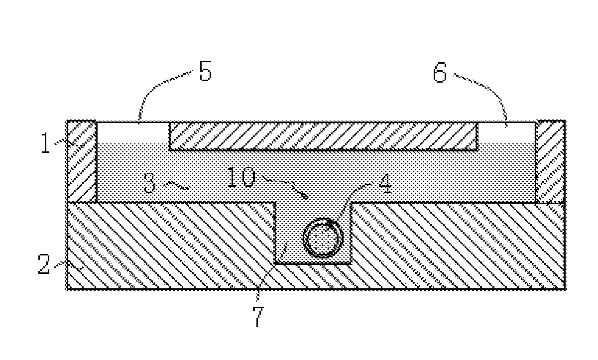
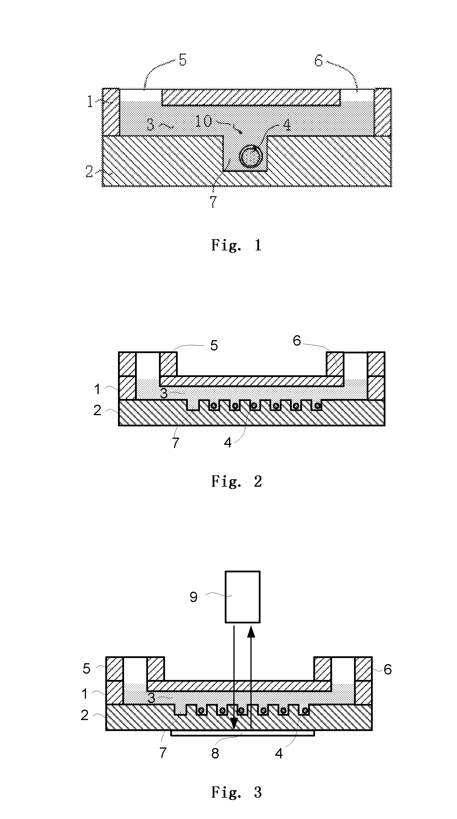
[0058]FIG. 1 illustrates one embodiment of the present invention of microfluidic chip which comprises an upper micro-channel layer 1 and a lower micro-well array layer 2, and the upper micro-channel layer 1 is closely connected to the lower micro-well layer 2. Micro-channel 3 is designed to be at the bottom of layer 1 and in close contact with layer 2, which has a height greater than the diameter of oocyte transported through it. On the micro-channel layer 1, inlet 5 and outlet 6 are also designed to be connected to the micro-channel 3, which have flexible structures, such as holes or wells (as shown in FIG. 2), or set as interfaces to be connected to other channels. On the micro-well array layer 2, more than one micro-wells 7 are included to trap oocyte 4, which are distributed to form an array both in parallel and vertical to the fluidic direction.

[0059]In the above embodiment, oocyte 4 is transferred by culture medium, along the micro-channel 3 in micro-channel layer 1 to the top...

example 2

[0062]FIG. 2 illustrates one embodiment of the present invention wherein the micro-well array covers the entire width of micro-channel 3, and along the fluidic direction there is a shift between each row of micro-wells 7 (the shift is smaller than half of the width of the micro-well 7), so as to capture oocytes 4 in different positions in micro-channel 3. Furthermore, the intervals between two micro-wells 7 are smaller than the width of micro-wells 7, which facilitates the entrance by oocyte 4 into the micro-well 7.

[0063]In the above embodiment, the shape of micro-well 7 can be square, circle or in any other shapes. The size of micro-well 7 can be designed to fit the size of oocytes of different species, and its width should be larger than the diameter of hatched embryo in order to provide enough space for embryo development.

example 3

[0064]FIG. 3 illustrates one embodiment of the present invention of microfluidic chip which is integrated with an optical detection device such as an interferometer 9. When the materials of micro-channel layer 1 and micro-well array layer 2 are light transparent (e.g., PDMS, etc.), a reflective layer 8 can be placed beneath micro-well array layer 2, and an interferometer 9 can be set on top of micro-channel layer 1. Optical images of oocytes 4 can be obtained by the interferometer 9, providing real-time observation of the fertilization and development process.


PUM


Abstract

An integrated microfluidic device and its usage are provided. The microfluidic device comprises an upper layer (1) and a lower layer (2), wherein the lower layer (2) is bound to the upper layer (1). The upper layer (1) comprises a micro-channel (3) and the lower layer (2) comprises a micro-well (7) array. The micro-channel (3) is in fluidic connection with the micro-well (7) array, and the height of the micro-channel (3) is greater than the diameter of the oocyte (4) flowing through the micro-channel (3). The integrated microfluidic device has many advantages including low cost, high integration, and convenient operation, and has application prospects in reproductive medicine and the research of fertilization and embryo early development.

Description

TECHNICAL FIELD[0001]The present invention relates to an integrated microfluidic device and its uses for single oocyte trapping. The present invention further relates to methods of oocyte trapping, in vitro fertilization (IVF), liquid manipulation, and embryo culture and retrieval using the integrated microfluidic device.BACKGROUND ART[0002]In vitro fertilization, a medical technology by which oocyte cells are fertilized by sperms in vitro, is currently a major treatment for infertility in clinics. The standard protocols for clinical IVF practice include gametes collection, fertilization, liquid manipulation and embryo culture, with culture medium held in oil-covered drops in Petri dishes, and manipulation performed manually by pipetting. For these protocols, frequent pipetting of gametes is required, which is labor-intensive and time-consuming. Furthermore, fertilization and embryo culture require different media, therefore the zygotes have to be washed several times and transporte...

Claims


Application Information

Patent Timeline
Patent Type & Authority Applications(United States)
IPC IPC(8): A61B17/43
CPCA61B17/435B01L3/502761B01L2200/0652A61B17/43B01L2300/0851B01L2400/086B01L2200/0689C12M21/06C12M23/16C12M47/04
Inventor HAN, CHAOHUANG, GUOLIANGCHENG, JING
Owner CAPITALBIO CORP
Why Eureka
Try Eureka