
Pressure Actuated Catheter Valve

a catheter valve and actuator technology, applied in the direction of functional valves, water supply installations, catheters, etc., can solve the problems of inability to operate, associated hazards, and undesirable drug use,

Inactive Publication Date: 2013-08-08
I V ACCESS TECH
View PDF8 Cites 66 Cited by
  • Summary
  • Abstract
  • Description
  • Claims
  • Application Information

AI Technical Summary

Benefits of technology

The patent text describes the use of resilient materials in catheters and guide needles to improve their flexibility and ability to conform to the path of the vessel into which they are inserted. Resilient materials can include valves, dilators, and o-rings, which can reduce physical stresses and ensure proper fitting of the device components. Hubs can also be used to attach various external devices and features to the catheter or catheterization device. Additionally, the text discusses the use of tapered tips and flash cups to aid in the insertion of the device and detect when the vessel wall has been punctured.

Problems solved by technology

Of course, such an arrangement introduces a poorly flushed dead leg in the system that interferes with fluid transfers and can present an environment for microbial growth.
However, these operations are problematic.
As a preliminary matter, the operations require manipulation of a needle, with its associated hazards.
In addition, in many cases it can be undesirable to have the drug diluted in the IV fluid during injection, or a blood sample diluted with IV fluid as it is withdrawn.
However, the devices cause significant fluid displacement when the luer is pushed through the first seal, and can leave possibly contaminated fluids in the space between seals as the luer fitting is withdrawn.
Further, the multiple seals are unduly complex, and increase the forces required to make the necessary connections.
In addition, the Desecki valve designs include a bulk of hardware in the flow path of the valve that can occlude fluid flow and increase forces necessary to open the valve.

Method used


Image

  • Pressure Actuated Catheter Valve
  • Pressure Actuated Catheter Valve
  • Pressure Actuated Catheter Valve

Examples


example 1

A Catheter Insertion Assembly

[0105]An exemplary catheter assembly was manufactured including a guide needle for perforation of skin and vessel; a guide dilator to expand the needle perforation, protect the vessel from further perforations and to guide a catheter into the vessel; and, a catheter to provide access to the vessel by clinical technicians. The assembly included a resilient valve, e.g., in the catheter hub and traversed by the needle and dilator.

[0106]FIG. 3 shows a catheter insertion assembly 30 composed of a guide needle 31, typically formed from stainless steel; a guide dilator 32, typically a tough, flexible plastic such as polyurethane or polytetrafluoroethylene; and, an intra-vascular catheter 33, also produced from a tough, flexible material, and of a geometry needed for a given medical procedure. These three components of the invention were fitted together concentrically such that the proximal end 34 of the guide needle protruded from the proximal end 35 of the gui...

example 2

Valve Configurations

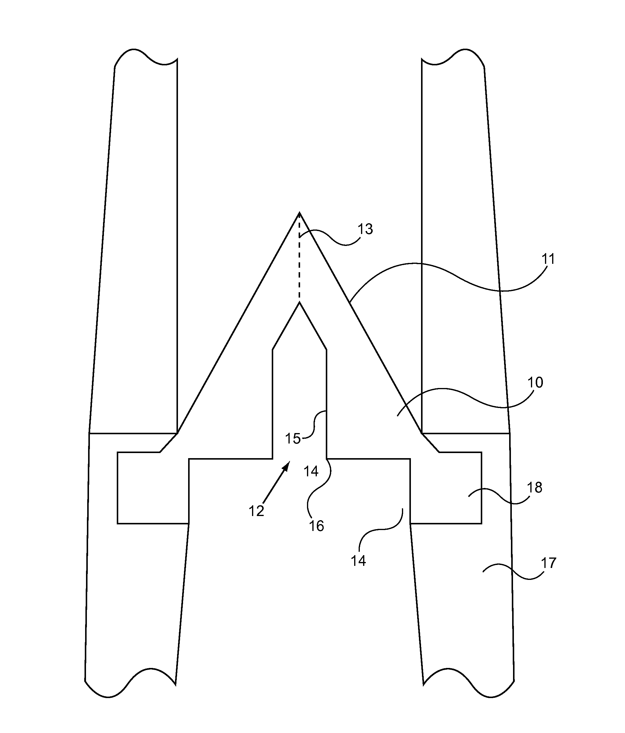
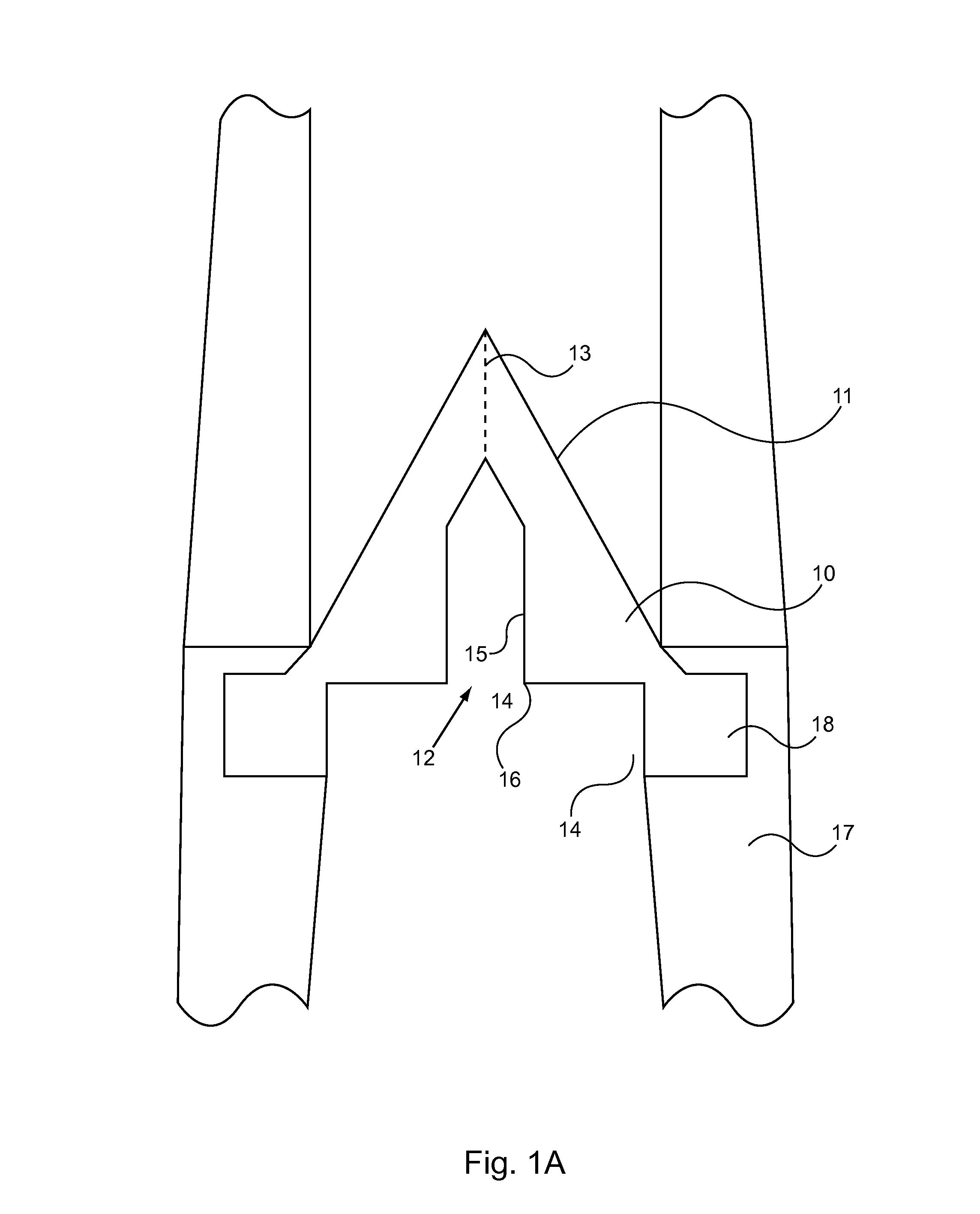
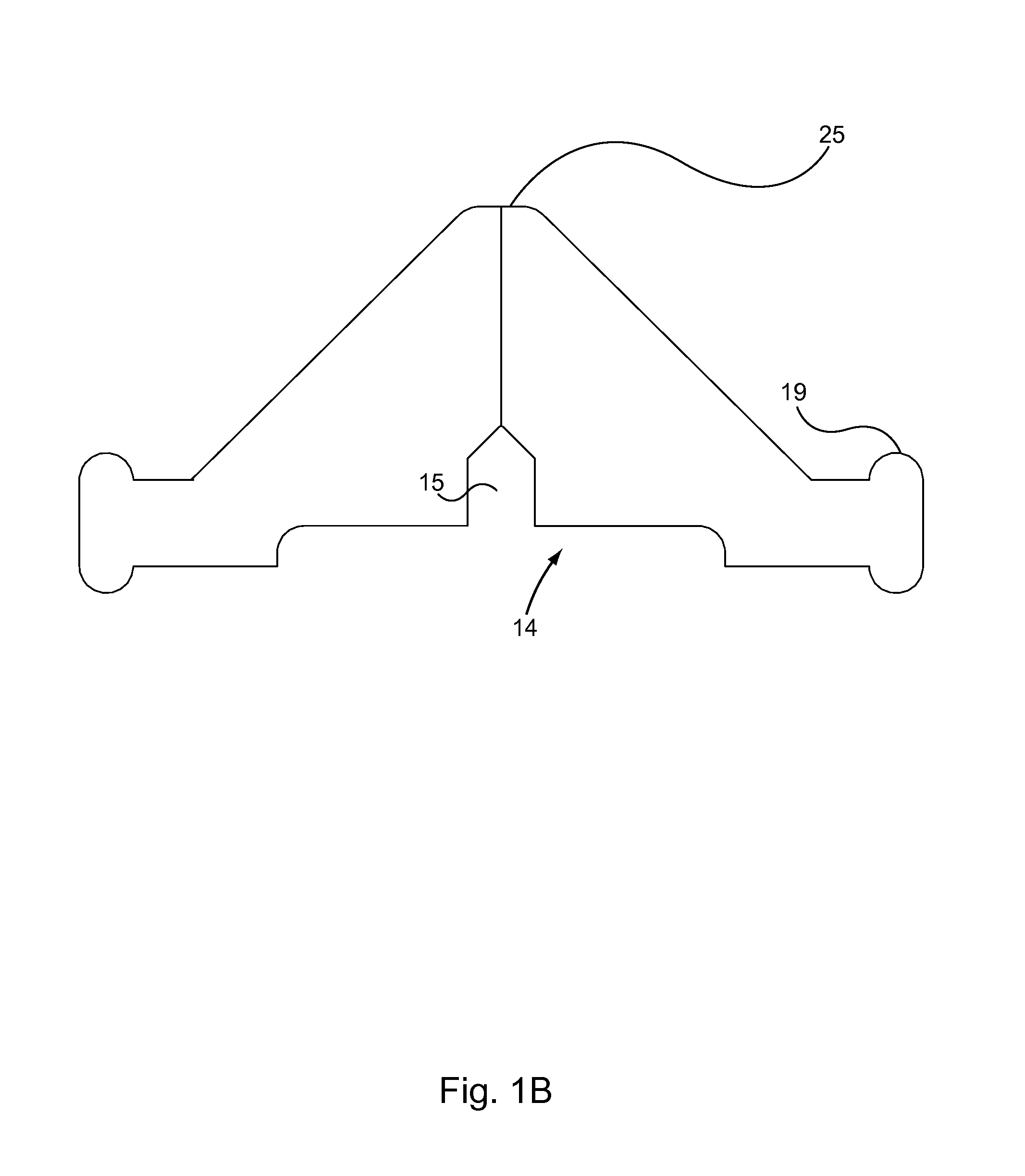
[0108]FIG. 4 shows an oblique view of the one way valve 40. The valve is composed of an outer flange 41, where it is held in position in the proximal hub of a catheter. The valve includes generally conical shaped distal surface 42, slits 43, and proximal surface 44. The proximal surface includes a first recess 45 and second recess 46, defining shoulder 48 where the edge of the first recess meets the second recess.

[0109]Note that slits 43 run from the apex of the tapered distal surface, through the body of the valve to the proximal side, ending at a point between the shoulder 48 and the outer wall 50 of the first recess 45. In this example, the valve flaps 51 comprise most of the valve body except the flange 41.

[0110]It is understood that the examples and embodiments described herein are for illustrative purposes only and that various modifications or changes in light thereof will be suggested to persons skilled in the art and are to be included within the spirit ...


PUM


Abstract

This invention provides catheter assemblies and methods for insertion of a catheter into a vessel. The assemblies include a resilient valve in the hub of the catheter that can be opened by pressure from a male luer fitting. The methods include piercing a vessel with the needle and catheter of the assembly, retraction of the needle component thus closing the resilient valve. Finally the catheter can be accessed by applying a male luer fitting to the catheter hub and a shoulder of the resilient valve.

Description

CROSS-REFERENCE TO RELATED APPLICATIONS[0001]This application claims priority to and benefit of a prior U.S. Provisional Application No. 61 / 595,415, Pressure Actuated Catheter Valve, by Stephen Keyser, filed Feb. 6, 2012. The full disclosure of the prior application is incorporated herein by reference.FIELD OF THE INVENTION[0002]The invention is directed to methods and devices to facilitate sanitary connection of luer devices to inserted catheters. Catheter assemblies include resilient valves having a distal tapered side with slits defining one-way flaps toward the catheter. The proximal side or the valve can have a first recess with an inner shoulder defined by a second recess centered in the first recess. When pressure is applied to the shoulder, the valve flaps in the second recess can pivot out at pivot points in the first recess, providing an unobstructed fluid flow path past the flaps. In the methods, the valve can hold and seal in place a needle and dilator in the catheter, w...

Claims


Application Information

Patent Timeline
IPC IPC(8): A61M39/26A61M25/00
CPCA61M39/26A61M2039/242A61M2039/066A61M25/0097A61M2039/0633Y10T137/0324Y10T137/7837
Inventor KEYSER, STEPHEN RICHARD
Owner I V ACCESS TECH
Learn More