Combo Transducer and Combo Transducer Package

Inactive Publication Date: 2013-08-15
ASIA PACIFIC MICROSYST
View PDF0 Cites 17 Cited by
  • Summary
  • Abstract
  • Description
  • Claims
  • Application Information

AI Technical Summary

Benefits of technology

[0009]Therefore, it is one object of the present invention to provide a combo tra

Problems solved by technology

Nonetheless, juxtaposing multiple sensors on a single chip may result in a larger chip size.
On the other hand, respectively disposing electrical components on two op

Method used


Image

  • Combo Transducer and Combo Transducer Package
  • Combo Transducer and Combo Transducer Package
  • Combo Transducer and Combo Transducer Package

Examples


Example

[0030]Before the present invention is described in greater detail, it should be noted that like elements are denoted by the same reference numerals throughout the disclosure.

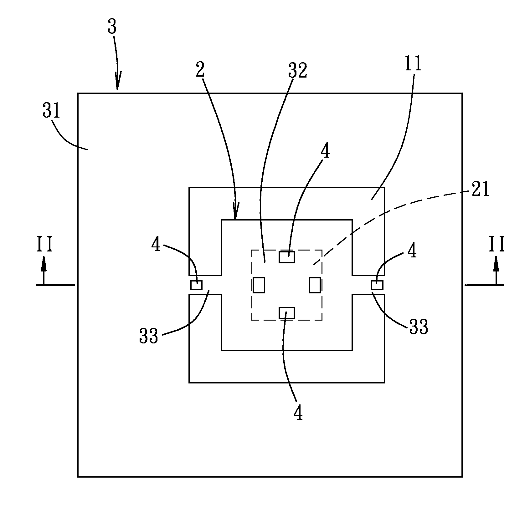
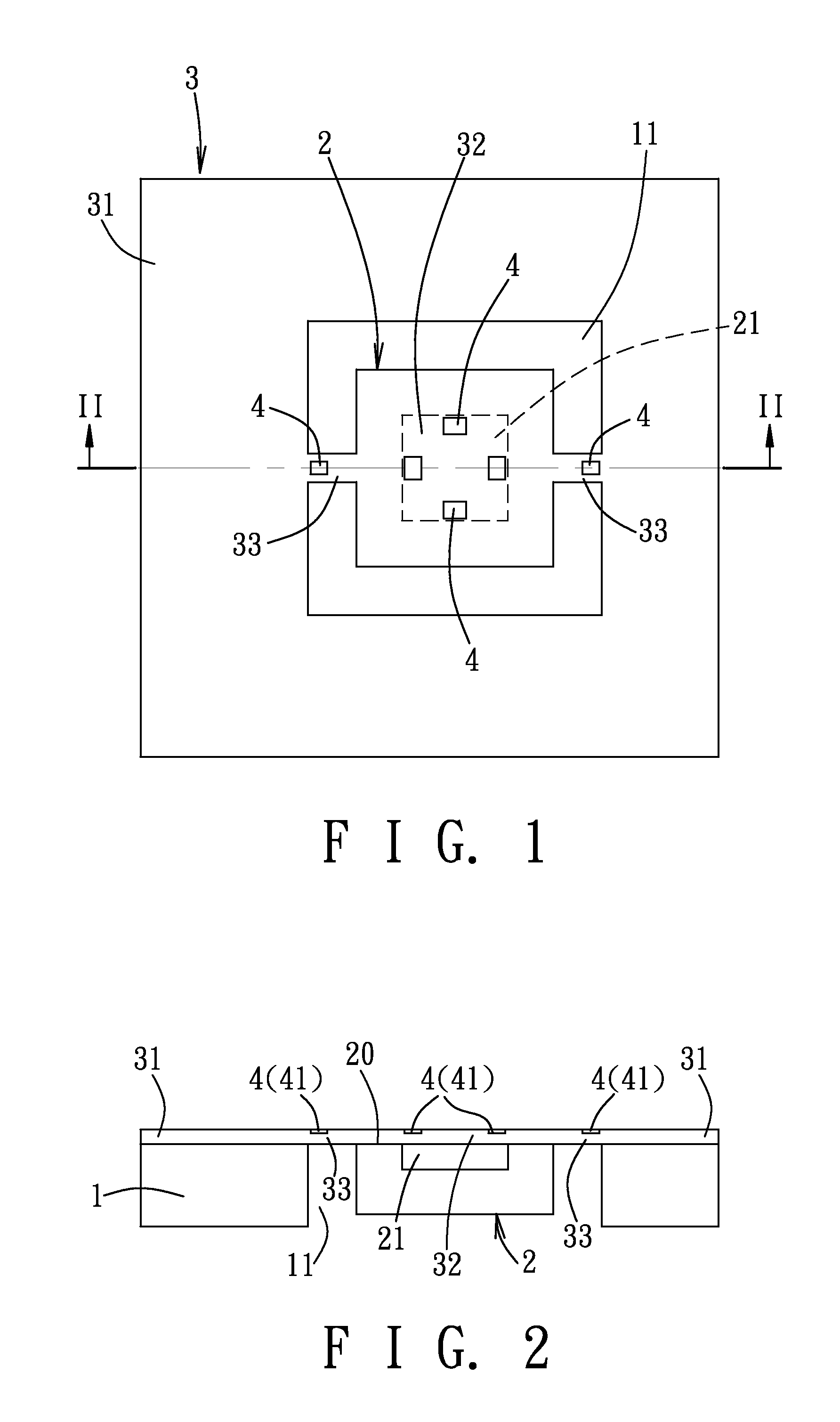
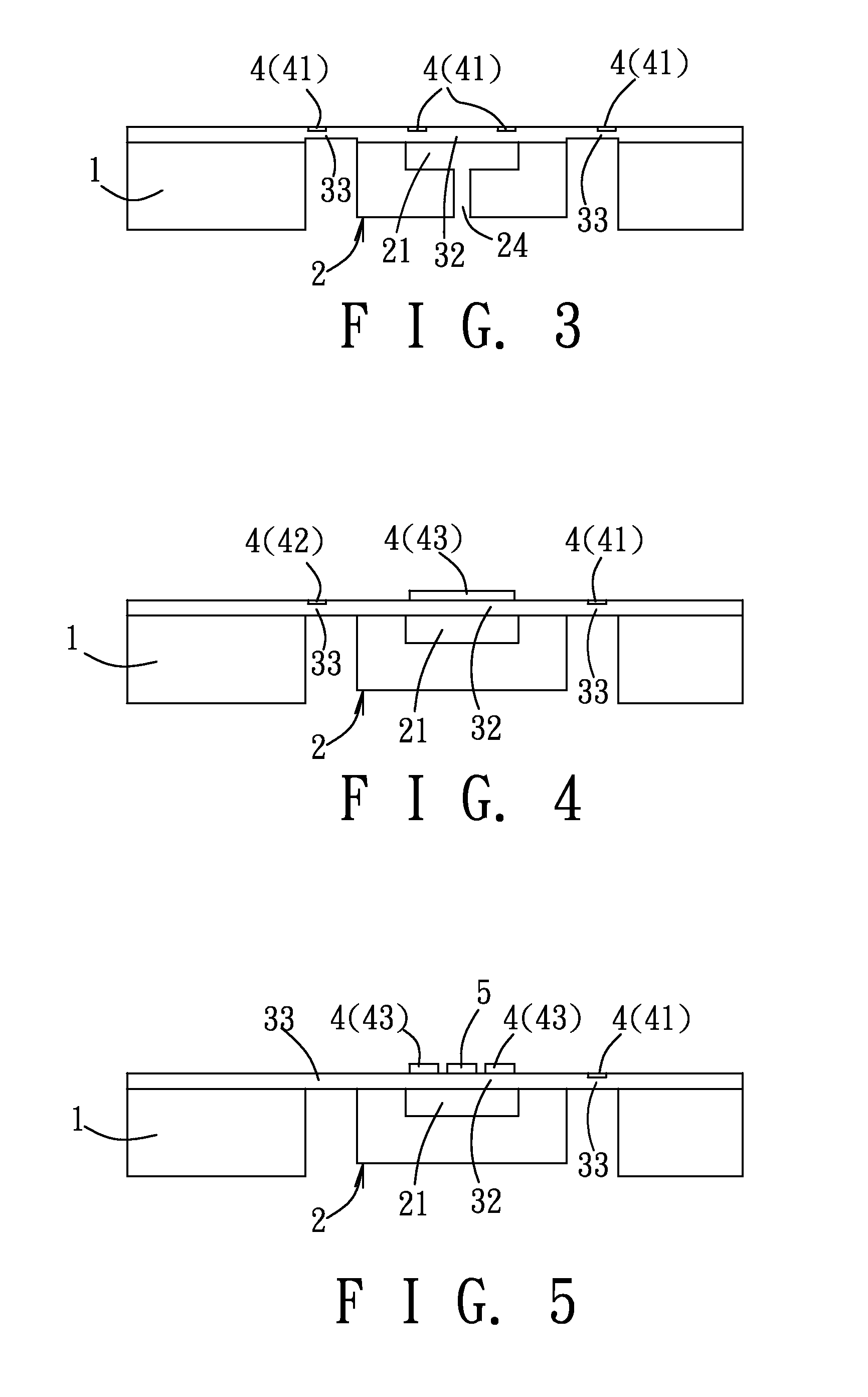
[0031]As shown in FIGS. 1 and 2, the first preferred embodiment of a combo transducer according to the present invention comprises a base 1, a proof mass 2, a membrane unit 3, and a plurality of transducing components 4.

[0032]The base 1 is formed with an aperture 11. The proof mass 2 is disposed in the aperture 11 and has a surface 20 that is formed with a cavity 21.

[0033]The membrane unit 3 includes a supporting part 31 connected to the base 2, a covering part 32, and two resilient linking parts 33. The covering part 32 is disposed to cover the surface 20 of the proof mass 2 and the cavity 21 enables the covering part 32 to deform and / or vibrate in response to pressure change. The resilient linking parts 33 interconnect the supporting part 31 and the covering part 32, such that the proof mass 2 is movable relat...


PUM


Abstract

A combo transducer includes a base, a proof mass, a membrane unit and a plurality of transducing components. The base is formed with an aperture. The proof mass is disposed in the aperture and has a surface that is formed with a cavity. The membrane unit includes a supporting part connected to the base, a covering part disposed to cover the surface of the proof mass, and a resilient linking part interconnecting the supporting part and the covering part such that the proof mass is movable relative to the base. The transducing components are disposed at the membrane unit. At least one of the transducing components is disposed at the covering part and is registered with the cavity.

Description

CROSS-REFERENCE TO RELATED APPLICATION[0001]This application claims priority of Taiwanese Application No. 101104710, filed on Feb. 11, 2012.BACKGROUND OF THE INVENTION[0002]1. Field of the Invention[0003]The invention relates to a transducer, more particularly to a combo transducer that has multiple functions and a relatively high system integration, and that can be manufactured using microelectromechanical system (MEMS) techniques.[0004]2. Description of the Related Art[0005]Microelectromechanical system (MEMS) is a technology that allows certain devices to be fabricated in very small scale. By combining semiconductor process and micromachining, various sensors and / or actuator components can be fabricated and implemented on a chip.[0006]It is noted that however, on many occasions, more than one physical quantity may be required to be measured. Taking an automobile as an example, an accelerometer and a gyroscope can be integrated on a single chip for measuring the acceleration and o...

Claims


Application Information

Patent Timeline
IPC IPC(8): G01P1/00
CPCG01P15/0802G01P15/123G01P1/00B81B2201/0278B81B2201/0235B81B2201/0264B81B7/02
Inventor WU, CHANG-WENHSIEH, JERWEIYEH, WU-CHENYIN, HUNG-LINHSI, HUAI-WEI
Owner ASIA PACIFIC MICROSYST
Why Eureka
Try Eureka