Single-column trash compactor

Active Publication Date: 2013-08-15
IACOBUCCI HF ELECTRONICS
View PDF9 Cites 7 Cited by
  • Summary
  • Abstract
  • Description
  • Claims
  • Application Information

AI Technical Summary

Benefits of technology

[0012]The invention also relates to the combination of the compactor device according to the invention with a trolley which is able to house the compactor device according to the invention and which also allows it to be moved inside the transportation means and to be arranged efficiently inside the spec

Problems solved by technology

For a long time the compactors were operated by means of hydraulic systems which meant that it was difficult to adapt them for use on-board aircraft.
These hydraulic systems in lace increased significantly the volume of the compaction device and resulted m the need for a large amount of electric power, the use of a large quantity of pressurized oil fluid and activation and control systems which are structurally complex and difficult to manufacture and maintain.
Moreover, the device has the drawback that it must be progressively greased, for which operation it Must be removed from the compart

Method used


Image

  • Single-column trash compactor
  • Single-column trash compactor
  • Single-column trash compactor

Examples


Example

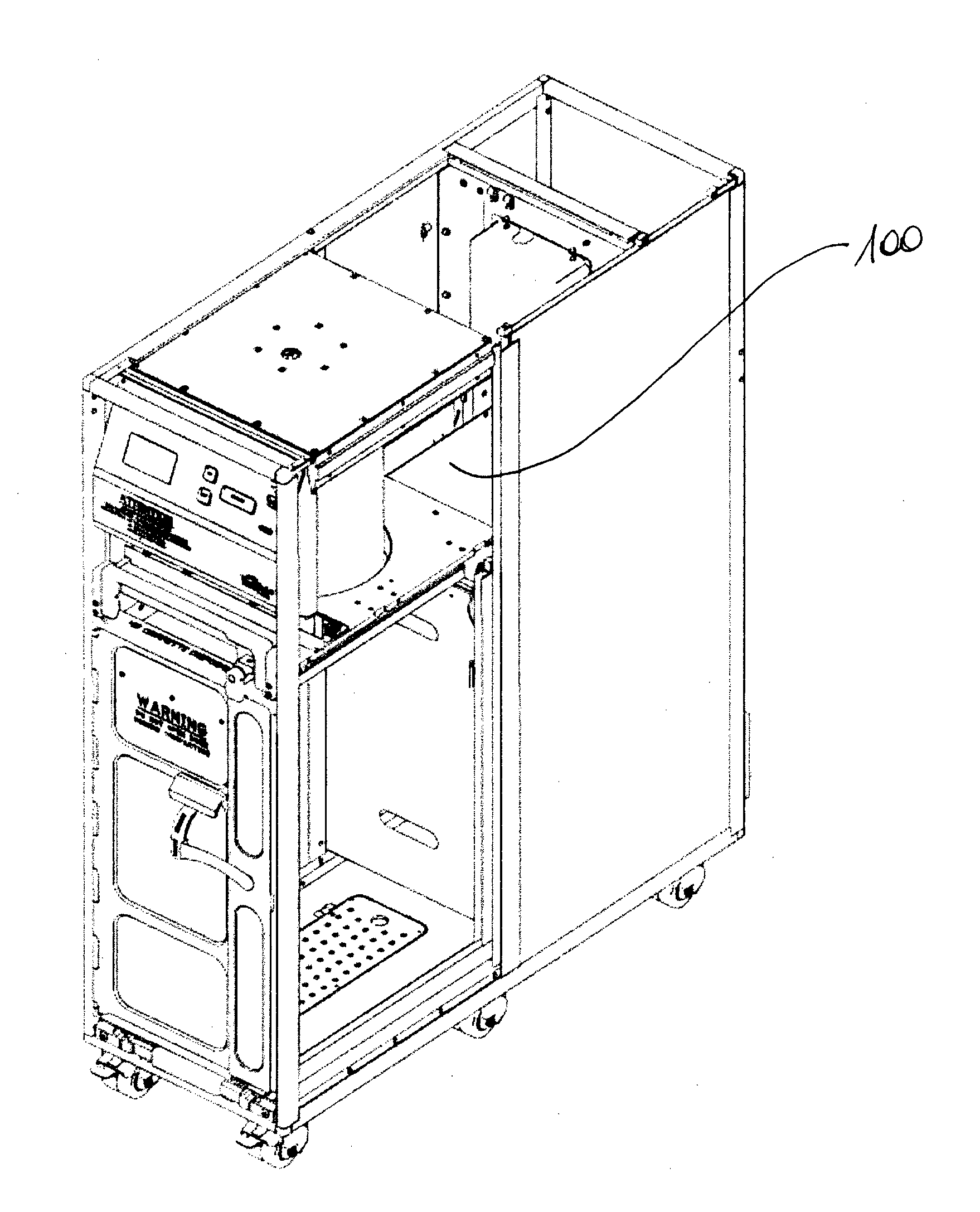
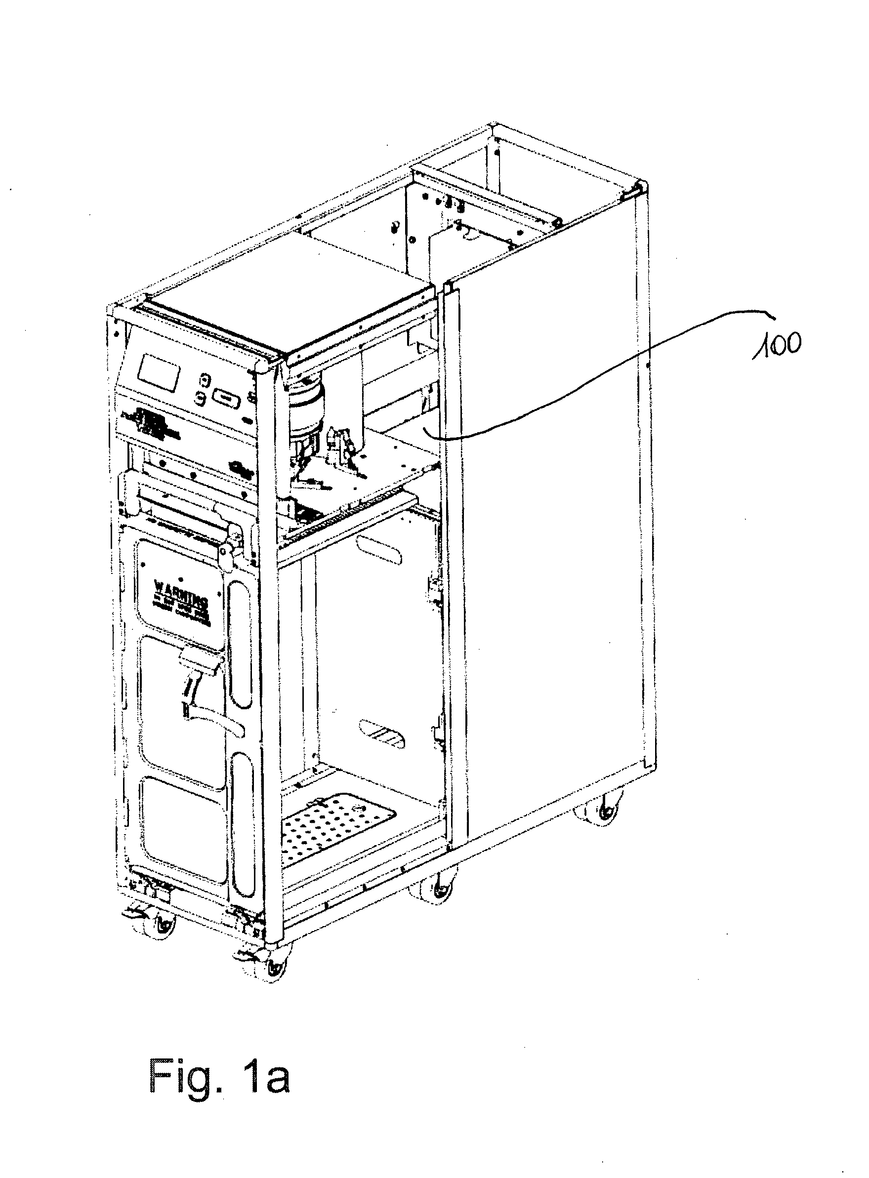
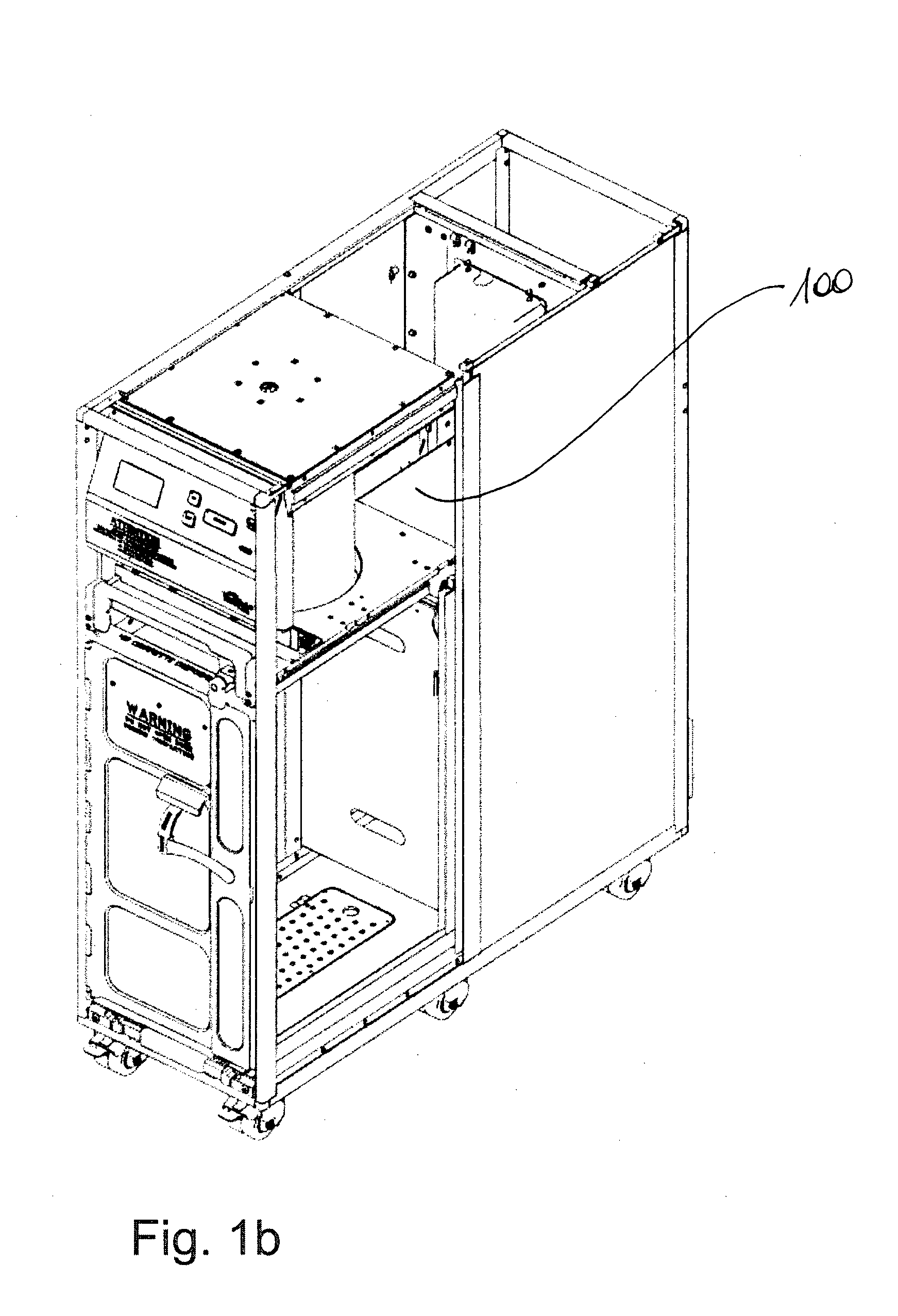
[0025]The compaction device according to the invention is of the single-column type, comprising a fixed part 1 for attachment to the carrying structure designed to house it by means of devices known per se, e.g. screws, and a movable compaction plate 4 which moves inside a trash collection compartment (not shown) for performing compaction of the trash. Fixed part 1 and movable plate 4 are connected together by means of a multiple-stage telescopic system for movement of the movable plate 4, preferably a telescopic system with recirculating ball screws, which is housed inside a jacket or cover, which is preferably substantially cylindrical and composed of a plurality of modules which are coaxial with each other, at least two, and preferably three modules, which are also telescopic, comprising a first module which is rigidly connected to the fixed part 1, an end module which is connected to the movable plate 4 and any other intermediate modules, which are moved together with the end mo...


PUM


Abstract

An electromechanical, modular, single-column, trash compactor with a particularly small size and low weight. In particular, a trash compaction device which can be used on-board aircraft, trains, ships and/or for civil applications and generally in all the locations and/or transportation means where the auxiliary service equipment must occupy as little space as possible. The compaction device is formed by a system of hollow telescopic screws (5,6), for example of the recirculating ball type, operated by a motor (2) housed inside the said screws (5,6). The compactor may be conveniently installed in compartments, which are fixed or movable on wheels, such as a trolley, so as to allow easy displacement thereof within the transportation means and insertion within the appropriate working spaces.

Description

FIELD OF THE INVENTION[0001]The present invention relates to an electromechanical, single-column, trash compactor designed with a telescopic screw system, for example, preferably of the recirculating bail type, operated by a motor housed inside screw.PRIOR ART[0002]The trash compactors used in particular in aircraft must satisfy special requirements as laid down in strict aeronautical regulations. In fact, the accessories installed on civil aircraft must have well-defined structural characteristics and dimensions since they must be able to satisfy a set of harsh requirements imposed by the existing regulations. They must, moreover, be housed and kept fixed safely inside the special compartments provided in the aircraft during flying conditions and must comply with the very strict weight requirement. In fact, a reduction in weight of each piece of accessory equipment on-board an aircraft results in significant savings with regard to fuel costs and management of the aircraft in the lo...

Claims


Application Information

Patent Timeline
IPC IPC(8): B65F1/14B30B1/18
CPCB30B1/18B30B9/3064B65F1/1468B65F1/1405B30B1/181
Inventor IACOBUCCI, LUCIO
Owner IACOBUCCI HF ELECTRONICS
Why Eureka
Try Eureka