Valve timing control apparatus for internal combustion engine
a timing control and internal combustion engine technology, applied in mechanical equipment, engines, machines/engines, etc., can solve problems such as inability to control the timing control apparatus, and achieve the effect of suppressing the deformation of the eccentric cam
- Summary
- Abstract
- Description
- Claims
- Application Information
AI Technical Summary
Benefits of technology
Problems solved by technology
Method used
Image
Examples
second embodiment
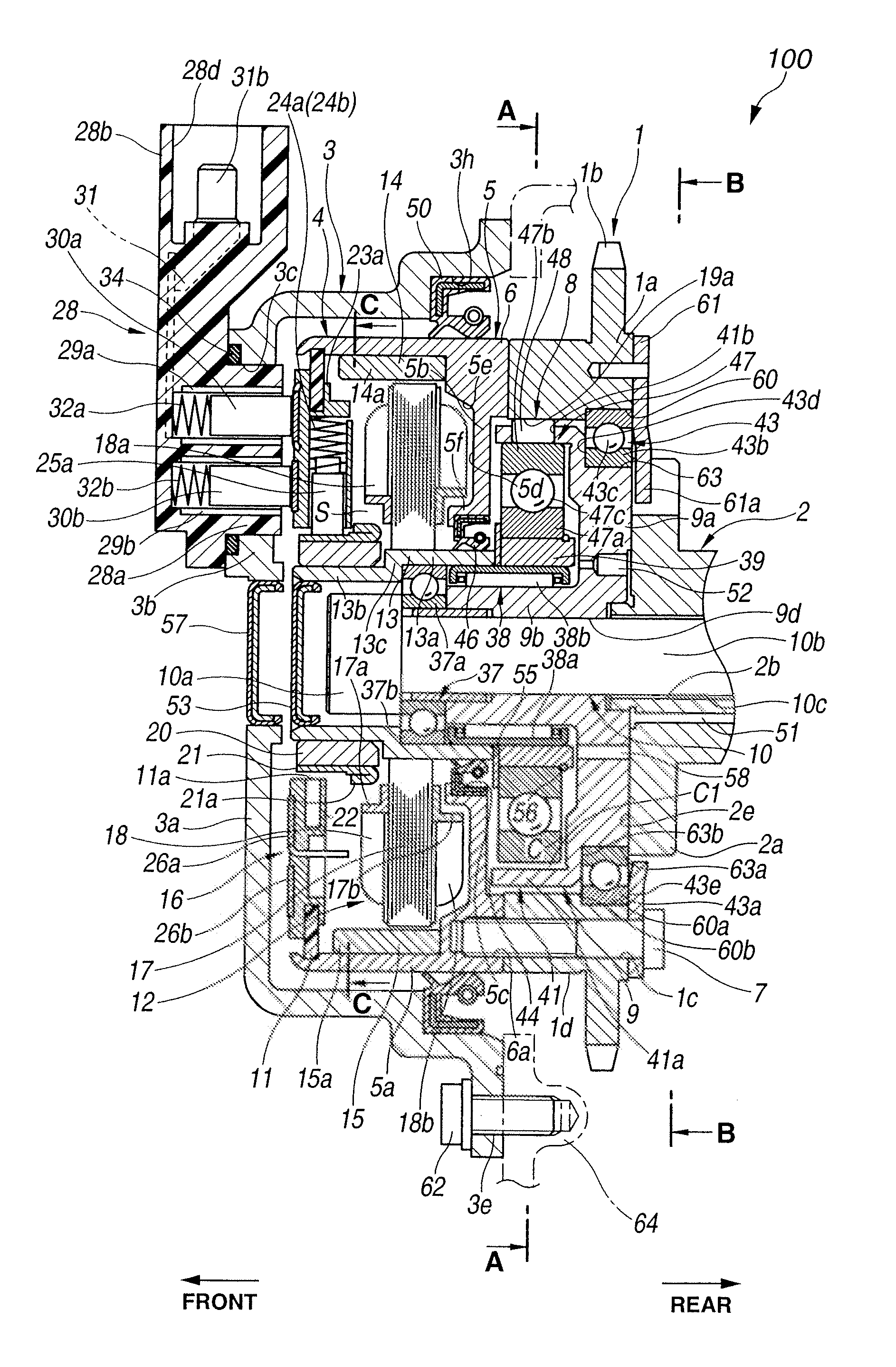
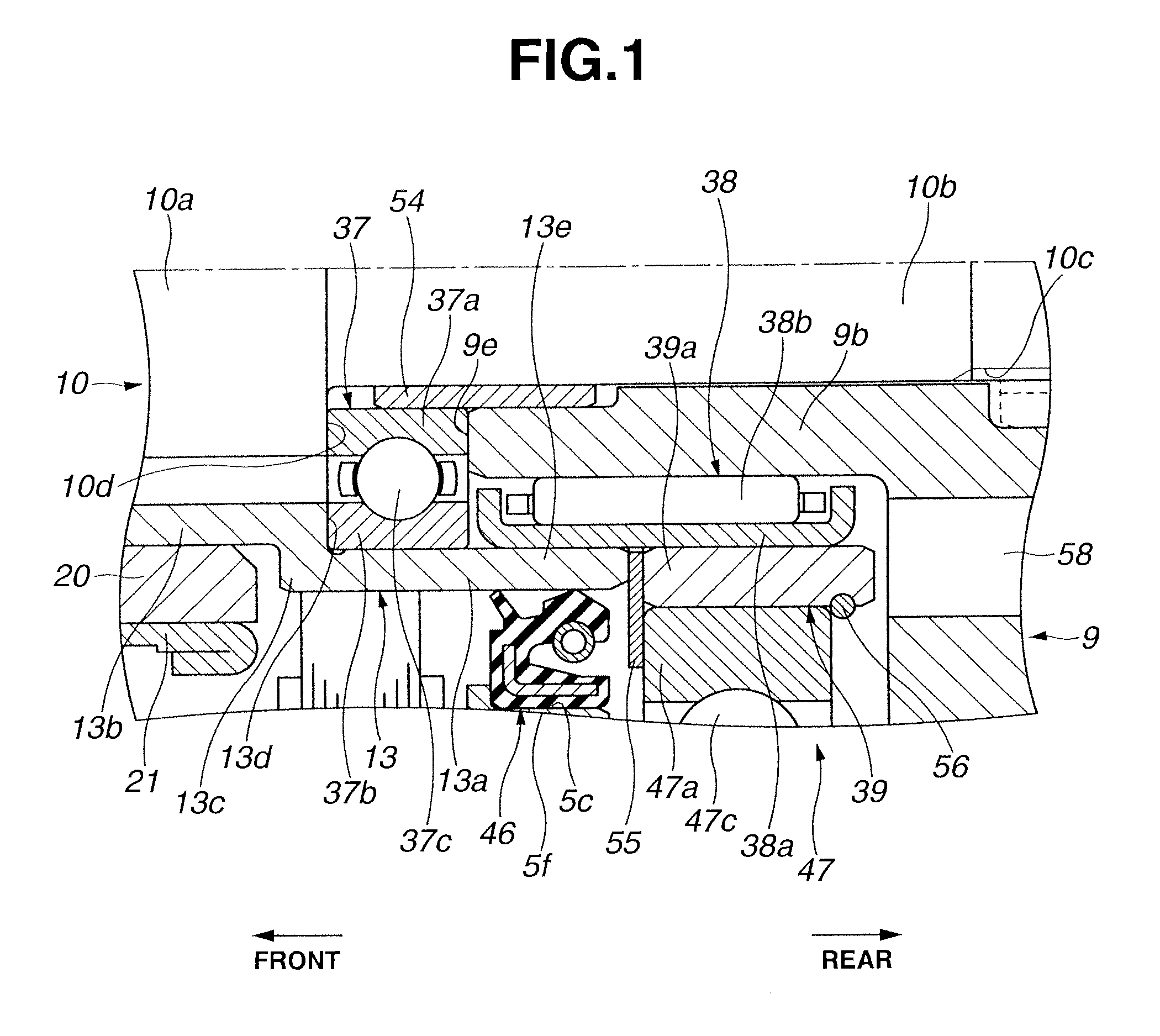
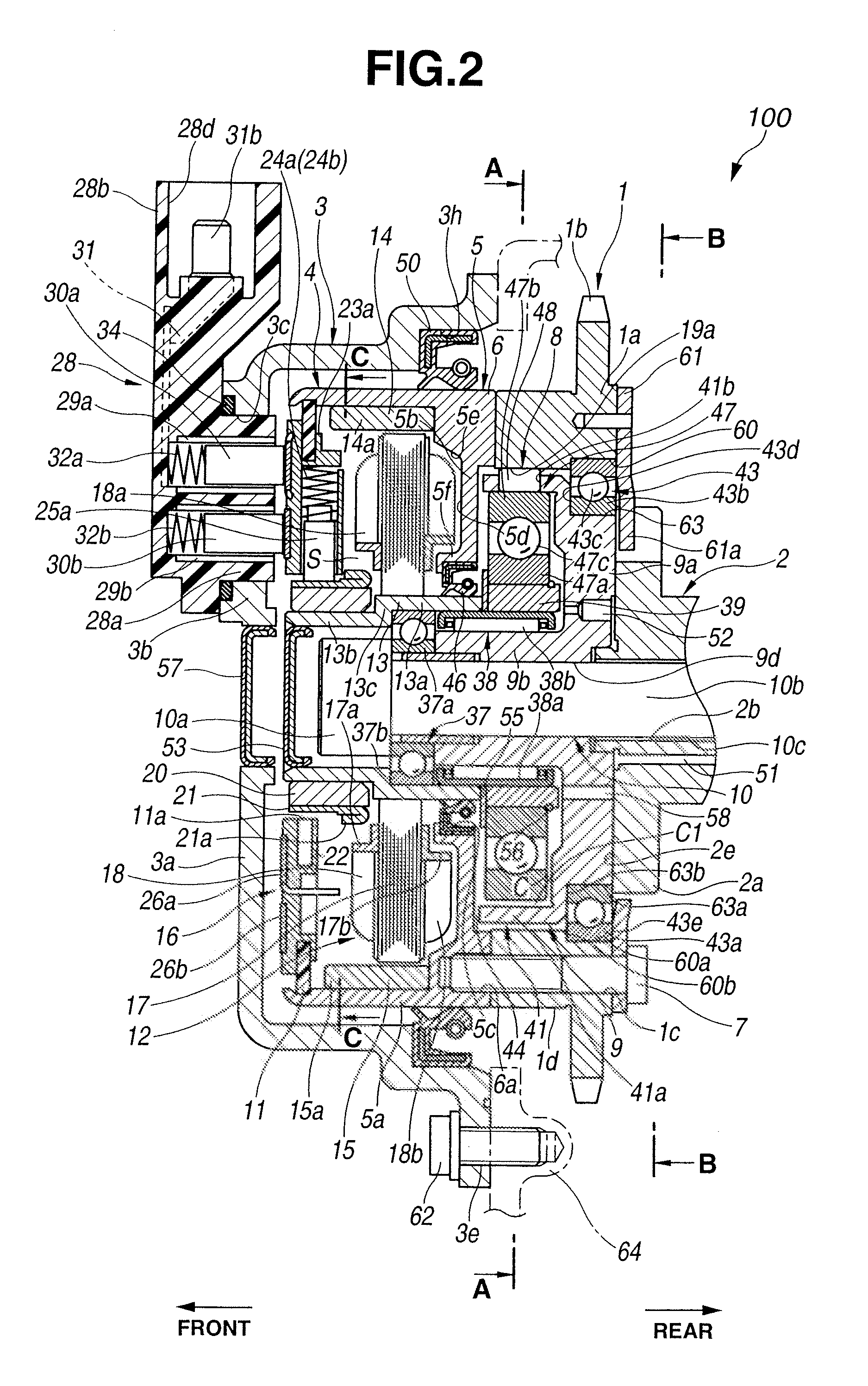
[0141]Referring to FIG. 7 and FIG. 8, valve timing control apparatus 200 according to a second embodiment will be explained hereinafter. The second embodiment differs from the first embodiment in construction of large-diameter portion 13a of motor shaft 13 and omission of washer 55. As shown in FIG. 7 and FIG. 8, in valve timing control apparatus 200, large-diameter portion 13a of motor shaft 13 has radial thickness Q slightly larger than that of small-diameter portion 13b, and axial length L increased by a thickness of washer 55 of the first embodiment.
[0142]An inner peripheral side of tip end surface (i.e., rear end surface) 13f of large-diameter portion 13a is contacted with the front end surface of eccentric cam 39 in the axial direction. On the other hand, an outer peripheral side of tip end surface 13f is contacted with a front end surface of inner race 47a of intermediate-diameter ball bearing 47. Accordingly, tip end surface 13f of large-diameter portion 13a and snap ring 56...
third embodiment
[0145]Referring to FIG. 9, valve timing control apparatus 300 according to a third embodiment will be explained hereinafter. The third embodiment differs from the first and second embodiments in construction of needle bearing 38, large-diameter portion 13a of motor shaft 13, and eccentric cam 39. As shown in FIG. 9, in valve timing control apparatus 300, needle bearing 38 has an outer diameter larger than those of the first and second embodiments. Further, large-diameter portion 13a of motor shaft 13 includes annular cutout portion 13g formed in the inner peripheral surface of tip end portion 13e. A front side of needle bearing 38 is disposed in cutout portion 13g. Further, eccentric cam 39 has a thickness slightly smaller than that of the first embodiment.
[0146]With the construction of needle bearing 38 having the larger outer diameter, it is possible to enhance rigidity of needle bearing 38 supporting motor shaft 13 and eccentric cam 39 and thereby increase strength of coupling be...
fourth embodiment
[0148]Referring to FIG. 10, valve timing control apparatus 400 according to a fourth embodiment will be explained hereinafter. The fourth embodiment differs from the first embodiment in construction of needle bearing 38 and large-diameter portion 13a of motor shaft 13, and omission of washer 55. As shown in FIG. 10, in valve timing control apparatus 400, needle bearing 38 has an outer diameter larger than those of the first and second embodiments. Further, large-diameter portion 13a of motor shaft 13 has radial thickness Q slightly larger than that of small-diameter portion 13b, and axial length L increased by a thickness of washer 55 of the first embodiment, like in the second embodiment. In the fourth embodiment, washer 55 can be omitted, and rigidity of needle bearing 38 supporting motor shaft 13 and eccentric cam 39 can be enhanced.
PUM
 Abstract
Description
Claims
Application Information
 - R&D
- Intellectual Property
- Life Sciences
- Materials
- Tech Scout
- Unparalleled Data Quality
- Higher Quality Content
- 60% Fewer Hallucinations
Browse by: Latest US Patents, China's latest patents, Technical Efficacy Thesaurus, Application Domain, Technology Topic, Popular Technical Reports.
© 2025 PatSnap. All rights reserved.Legal|Privacy policy|Modern Slavery Act Transparency Statement|Sitemap|About US| Contact US: help@patsnap.com


