Optical-based weld travel speed sensing system

a sensing system and welding torch technology, applied in the field of welding systems, can solve problems such as difficulty in measuring the travel speed of welding torch during welding operation

Active Publication Date: 2013-08-15
ILLINOIS TOOL WORKS INC
View PDF4 Cites 92 Cited by
  • Summary
  • Abstract
  • Description
  • Claims
  • Application Information

AI Technical Summary

Problems solved by technology

Unfortunately, it may be difficult to measure this weld motion during a welding operat

Method used


Image

  • Optical-based weld travel speed sensing system
  • Optical-based weld travel speed sensing system
  • Optical-based weld travel speed sensing system

Examples


Embodiment Construction

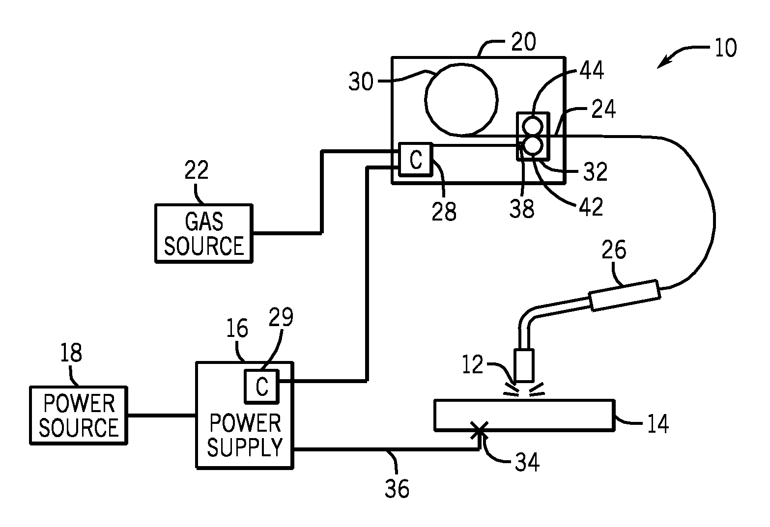
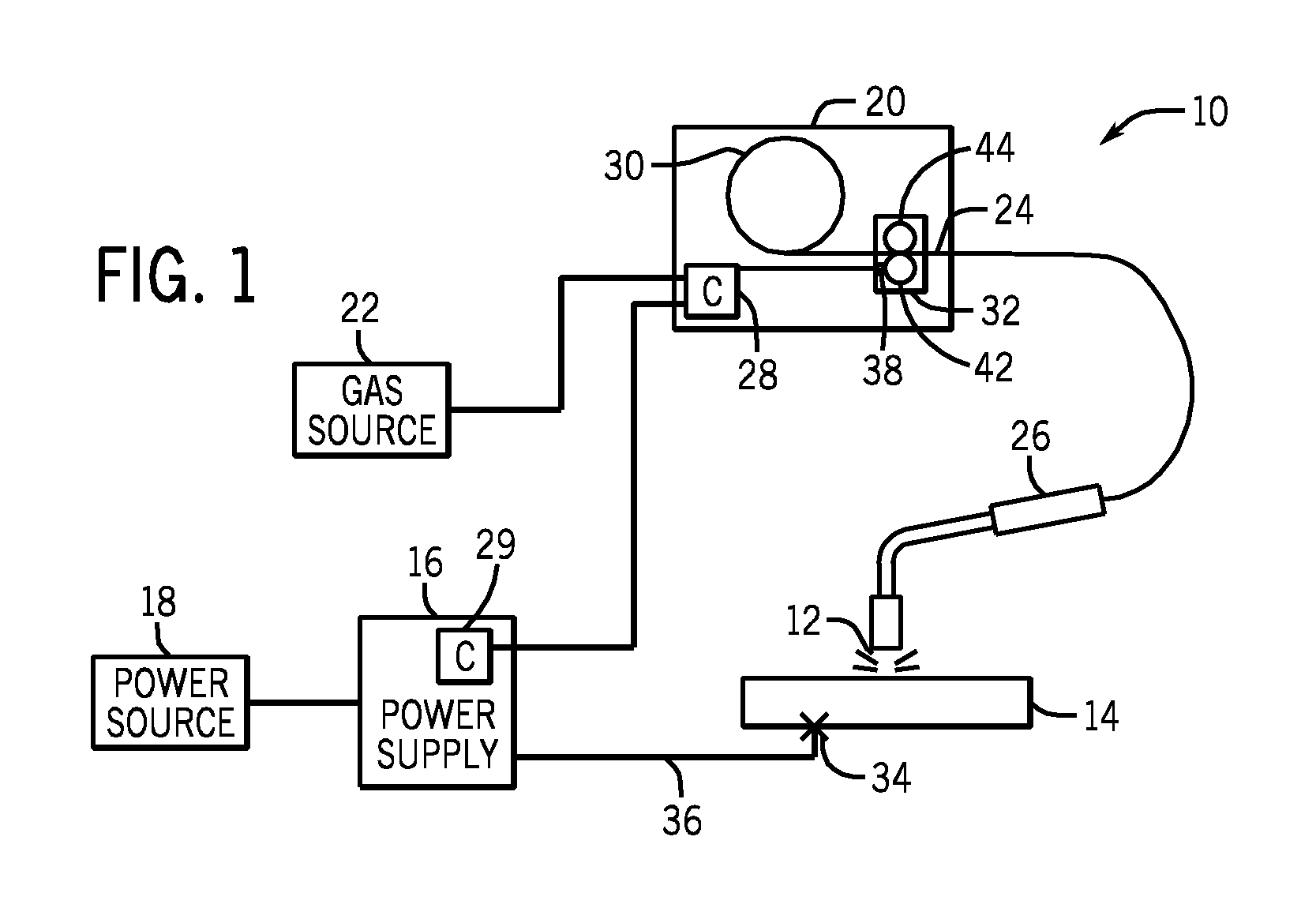
[0016]As described in detail below, provided herein are systems and methods for determining the travel speed of a welding device during a welding operation. The foregoing systems and methods may be used separately or in combination to obtain information during the welding operation relating to the three dimensional speed of the welding torch along the surface of the metal being welded. In some embodiments, these methods may be utilized in unconstrained or manual welding operations to offer advantages over traditional systems in which it may be difficult to measure the weld motion. However, the foregoing systems and methods may be utilized in a variety of suitable welding systems, such as automated or robotic systems.

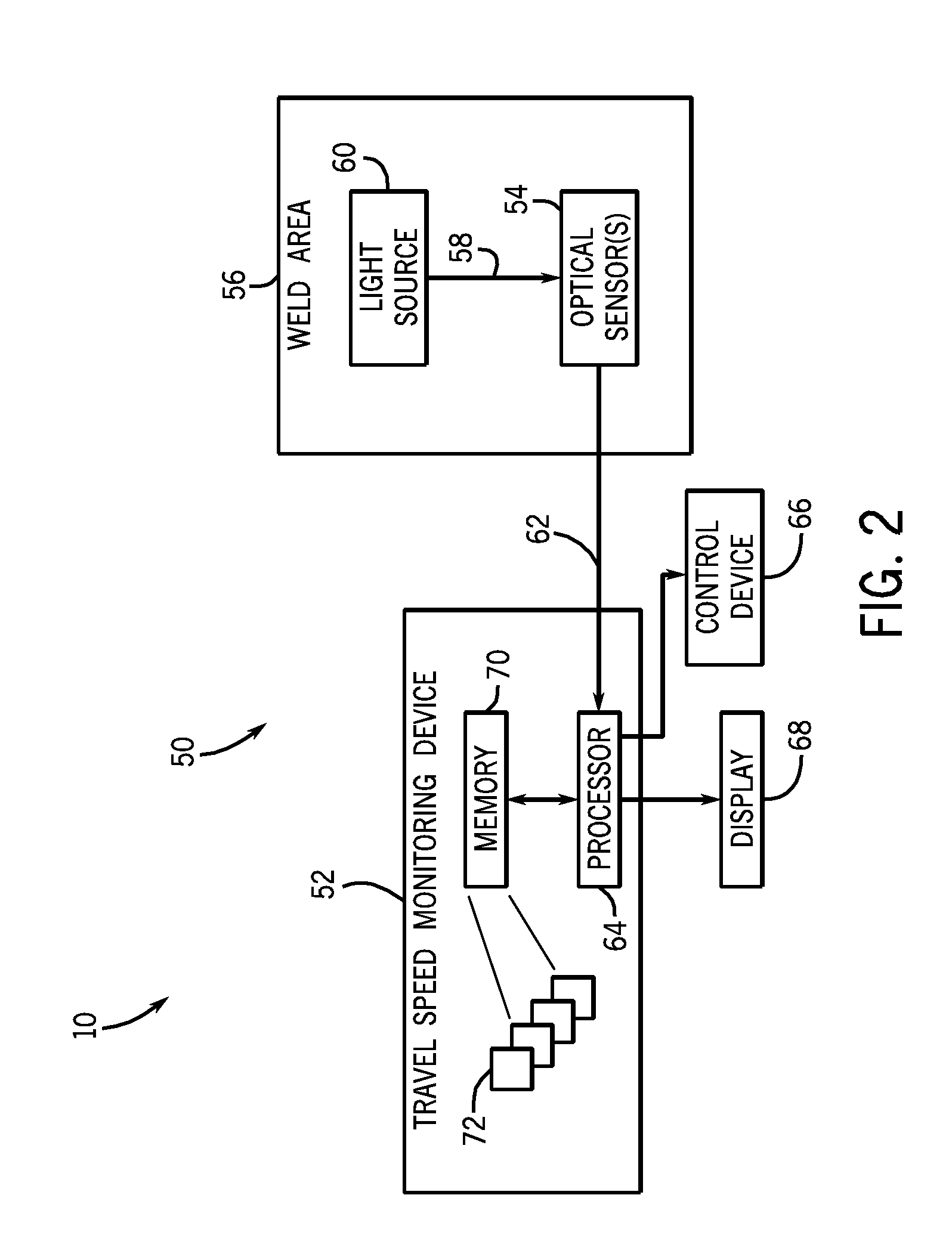
[0017]Present embodiments are directed toward systems and methods for sensing a travel speed of a welding torch using an optical detection system. More specifically, the disclosed systems include a travel speed sensing system that monitors a light or image associated wit...


PUM

PropertyMeasurementUnit
Speedaaaaaaaaaa
Areaaaaaaaaaaa
Distanceaaaaaaaaaa

Abstract

A travel speed sensing system includes an optical sensor configured to be coupled to a welding torch. The optical sensor is configured to sense light incident on the optical sensor, and the travel speed sensing system is configured to determine a travel speed of the welding torch, a direction of the welding torch, or both, based on the sensed light.

Description

CROSS REFERENCE TO RELATED APPLICATIONS[0001]This application is a Non-Provisional patent application of U.S. Patent Application No. 61 / 597,556, entitled “Weld Travel Speed Sensing Systems and Methods”, filed Feb. 10, 2012, which is herein incorporated by reference.BACKGROUND[0002]The invention relates generally to welding systems, and, more particularly, to sensing systems for monitoring a travel speed of a welding torch during a welding operation.[0003]Welding is a process that has become ubiquitous in various industries for a variety of types of applications. For example, welding is often performed in applications such as shipbuilding, aircraft repair, construction, and so forth. While these welding operations may be automated in certain contexts, there still exists a need for manual welding operations. In some manual welding operations, it may be desirable to monitor weld parameters, such as the travel speed of the welding torch, throughout the welding operation. While the trave...

Claims


Application Information

Patent Timeline
IPC IPC(8): G01P3/36B23K9/095
CPCB23K9/095G01P3/36G01S11/14G01P3/38B23K9/0956B23K9/0953G01S11/12G01S17/58
Inventor PFEIFER, KYLE ANDREWHOLVERSON, TODD EARLWATSON, WILLIAM TODDHUTCHISON, RICHARD MARTINBECKER, WILLIAM JOSHUA
Owner ILLINOIS TOOL WORKS INC
Why Eureka
Try Eureka