
Method for the detection and tracking of lane markings

a technology for detecting and tracking lane markings, applied in character and pattern recognition, instruments, computing, etc., can solve the problems of difficult to correctly detect all lane markings which are present in the image, and considerably impair the performance of a driver assistance system, and achieve reliable results.

Active Publication Date: 2013-08-15
APTIV TECH LTD
View PDF22 Cites 40 Cited by
  • Summary
  • Abstract
  • Description
  • Claims
  • Application Information

AI Technical Summary

Benefits of technology

The patent is about a method that can better detect lane markings and produce reliable results even in complex traffic situations. This makes it more robust and effective in its use.

Problems solved by technology

In particular, in the case of simultaneous monitoring of a plurality of lanes, it is difficult to correctly detect all lane markings which are present in the image.
This is because there are image objects which meet the detection criterion, but do not constitute valid lane markings.
Erroneous tracking of this kind can considerably impair the performance of a driver assistance system.

Method used


Image

  • Method for the detection and tracking of lane markings
  • Method for the detection and tracking of lane markings
  • Method for the detection and tracking of lane markings

Examples


Embodiment Construction

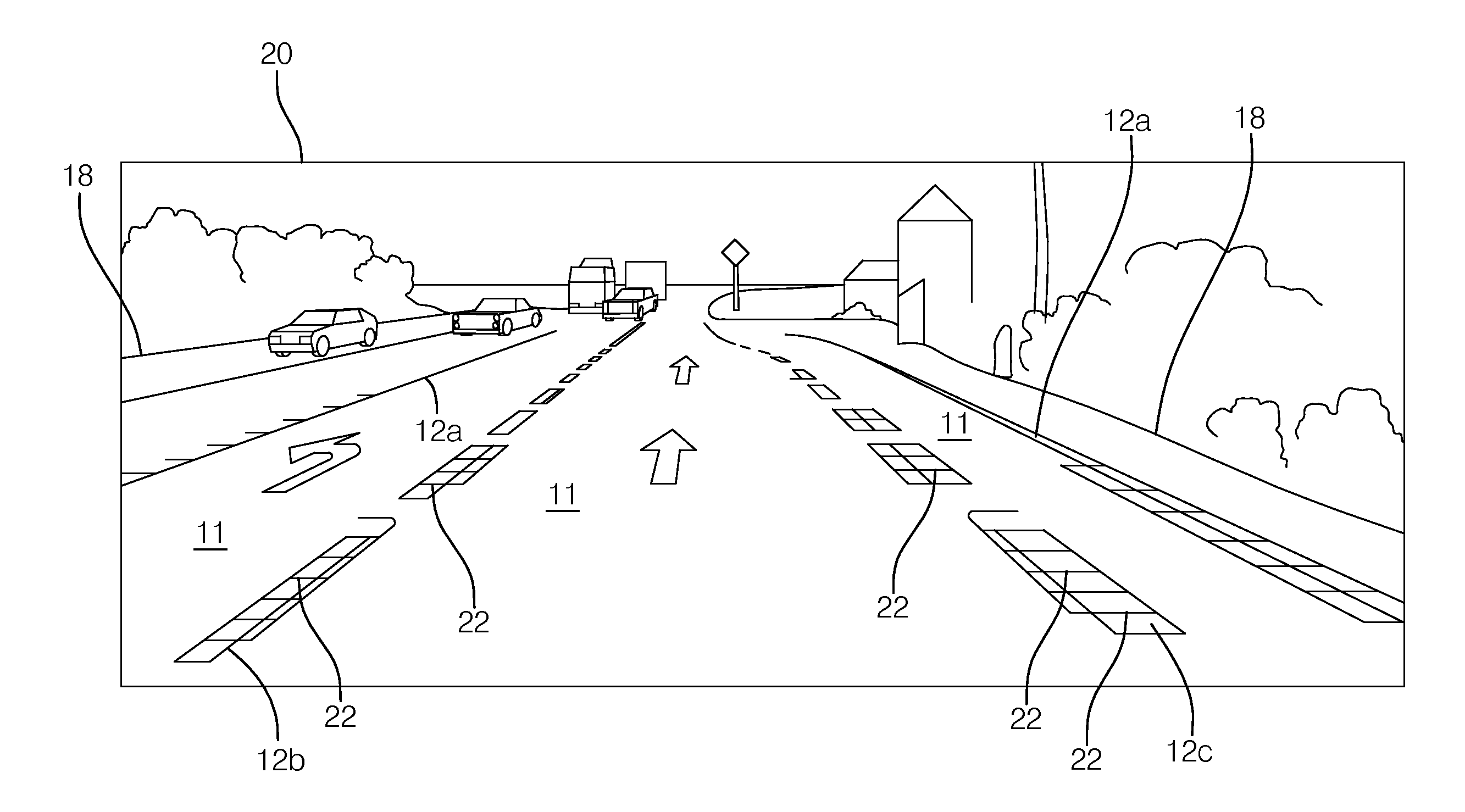
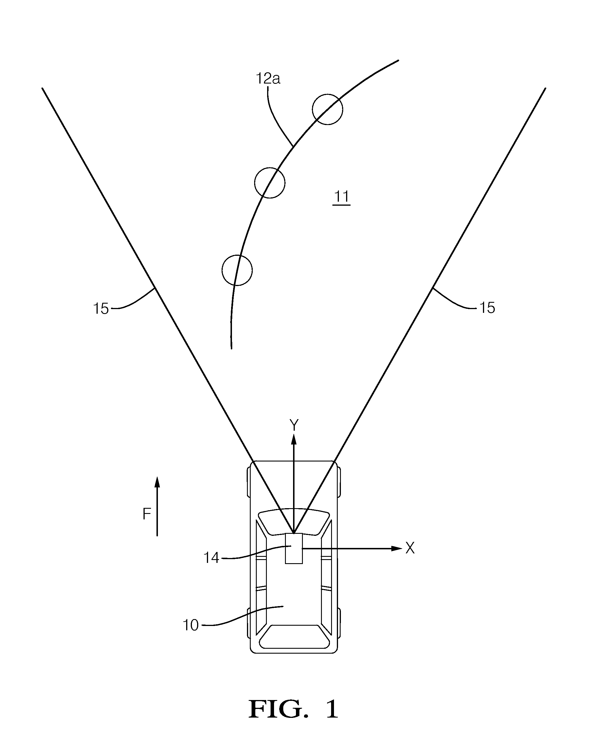
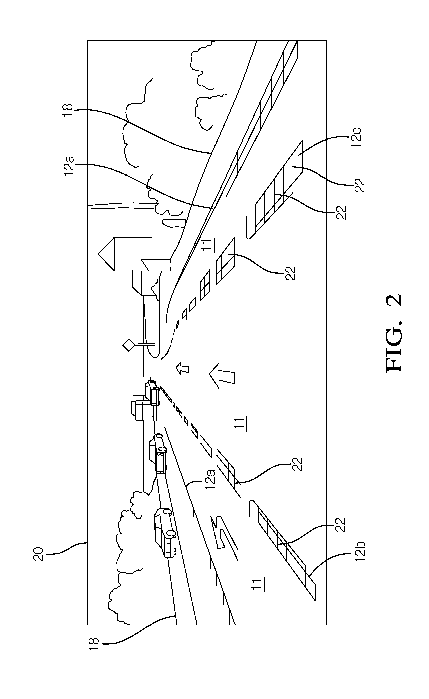
[0033]According to FIG. 1, a motor vehicle 10 is moving forwards in a direction of travel F in the lane 11 of a road. The lane 11 is defined by a left lane marking 12a in the form of an unbroken line and by a right lane marking, not shown. A camera 14 is mounted on the vehicle 10 at, for example, a front region of the vehicle, such as a roof lining of the vehicle interior. The camera 14 is generally configured to capture continuously an image (i.e. a sequence or series of image frames) of the space located in front of the vehicle 10, for example, the area between sight rays 15. The area viewed by the camera 14 may be characterized according to a world coordinate system having x and y distance values. Furthermore, the camera 14 is coupled to an image processing computer (not shown) to form an image processing system that is generally configured to process the images provided by the camera 14. The image processing computer may be housed within the camera 14, or may be located elsewher...


PUM


Abstract

In a method for the detection and tracking of lane markings from a motor vehicle, an image of a space located in front of the vehicle is captured by means of an image capture device at regular intervals. The picture elements that meet a predetermined detection criterion are identified as detected lane markings in the captured image. At least one detected lane marking as a lane marking to be tracked is subjected to a tracking process. At least one test zone is defined for each detected lane marking. With the aid of intensity values of the picture elements associated with the test zone, at least one parameter is determined. The detected lane marking is assigned to one of several lane marking categories, depending on the parameter.

Description

CROSS-REFERENCE TO RELATED APPLICATION[0001]This application claims the benefit under 35 U.S.C. §119(a) of European Patent Application EP 12000978.2, filed Feb. 15, 2012, the entire disclosure of which is hereby incorporated herein by reference.TECHNICAL FIELD OF INVENTION[0002]This disclosure generally relates to detecting roadway lane markings, and more particularly relates to a method for the detection and tracking of lane markings from a motor vehicle equipped an image capture device.BACKGROUND OF INVENTION[0003]The tracking of lane markings is important for various kinds of driver assistance systems in modern motor vehicles. For example, a lane departure warning (LDW) can use the tracking of lane markings to determine the position of the vehicle within the lane and emits a warning signal if it gets too close to the edge of the lane. Lane keeping support (LKS) systems are also known. Such system supports the driver with keeping to the present lane by continuous steering, braking...

Claims


Application Information

Patent Timeline
Patent Type & Authority Applications(United States)
IPC IPC(8): G06K9/78
CPCG06K2009/3291G06K9/00798G06V20/588G06V10/62
Inventor NUNN, CHRISTIANMEUTER, MIRKOMUELLER, DENNISGOERMER, STEFFEN
Owner APTIV TECH LTD
Learn More