Midplane Orthogonal Connector System

a technology of orthogonal connectors and connectors, applied in the field of electric connectors, can solve the problems of limited contact density limitations of conventional orthogonal connectors

Active Publication Date: 2013-08-15
TYCO ELECTRONICS LOGISTICS AG (CH)
View PDF5 Cites 79 Cited by
  • Summary
  • Abstract
  • Description
  • Claims
  • Application Information

AI Technical Summary

Problems solved by technology

However, conventional orthogonal connectors have experienced certain limitations.
Heretofore, the contact density has been limited in orthogonal connectors, due to the contact and via patterns.

Method used


Image

  • Midplane Orthogonal Connector System
  • Midplane Orthogonal Connector System
  • Midplane Orthogonal Connector System

Examples


Embodiment Construction

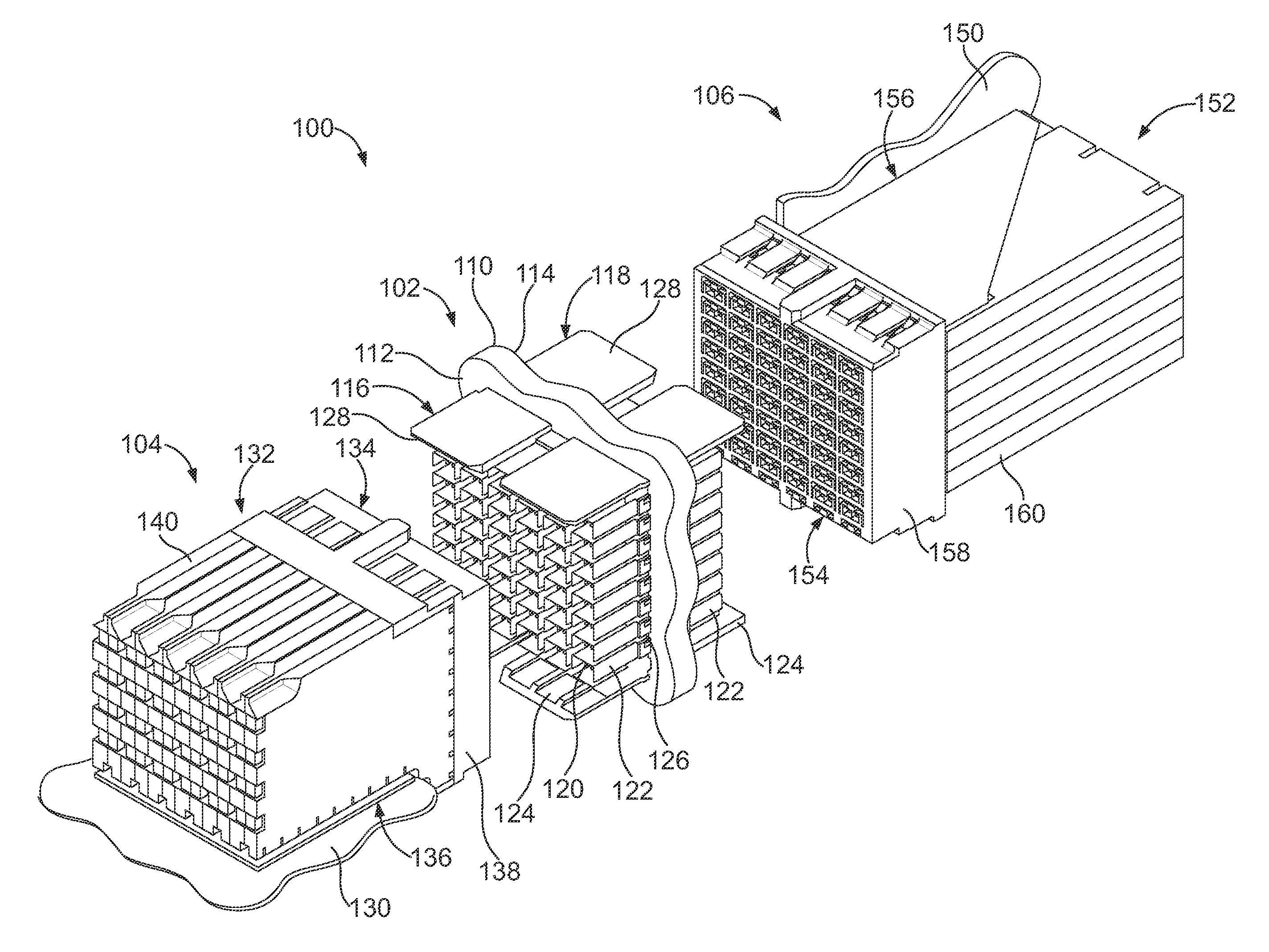
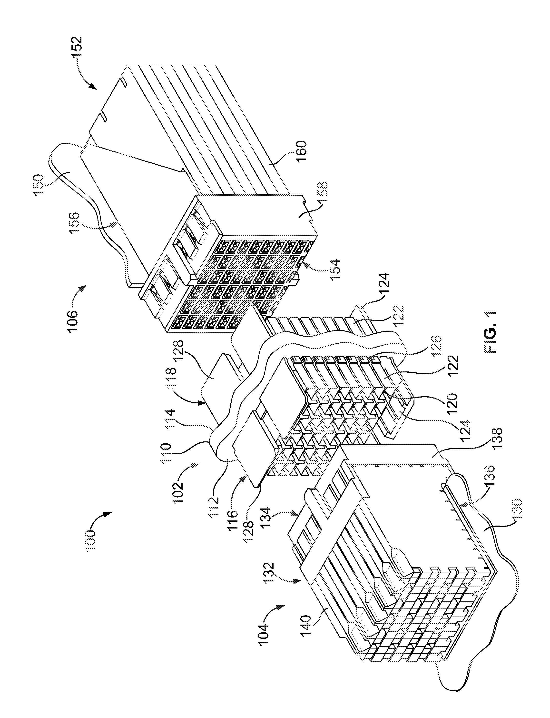
[0019]FIG. 1 is a perspective view of a midplane connector system 100 formed in accordance with an exemplary embodiment. The midplane connector system 100 includes a midplane assembly 102, a first connector assembly 104 configured to be coupled to one side of the midplane assembly 102 and a second connector assembly 106 configured to be connected to a second side the midplane assembly 102. The midplane assembly 102 is used to electrically connect the first and second connector assemblies 104, 106. Optionally, the first connector assembly 104 may be part of a daughter card and the second connector assembly 106 may be part of a backplane, or vice versa. The first and second connector assemblies 104, 106 may be line cards or switch cards.

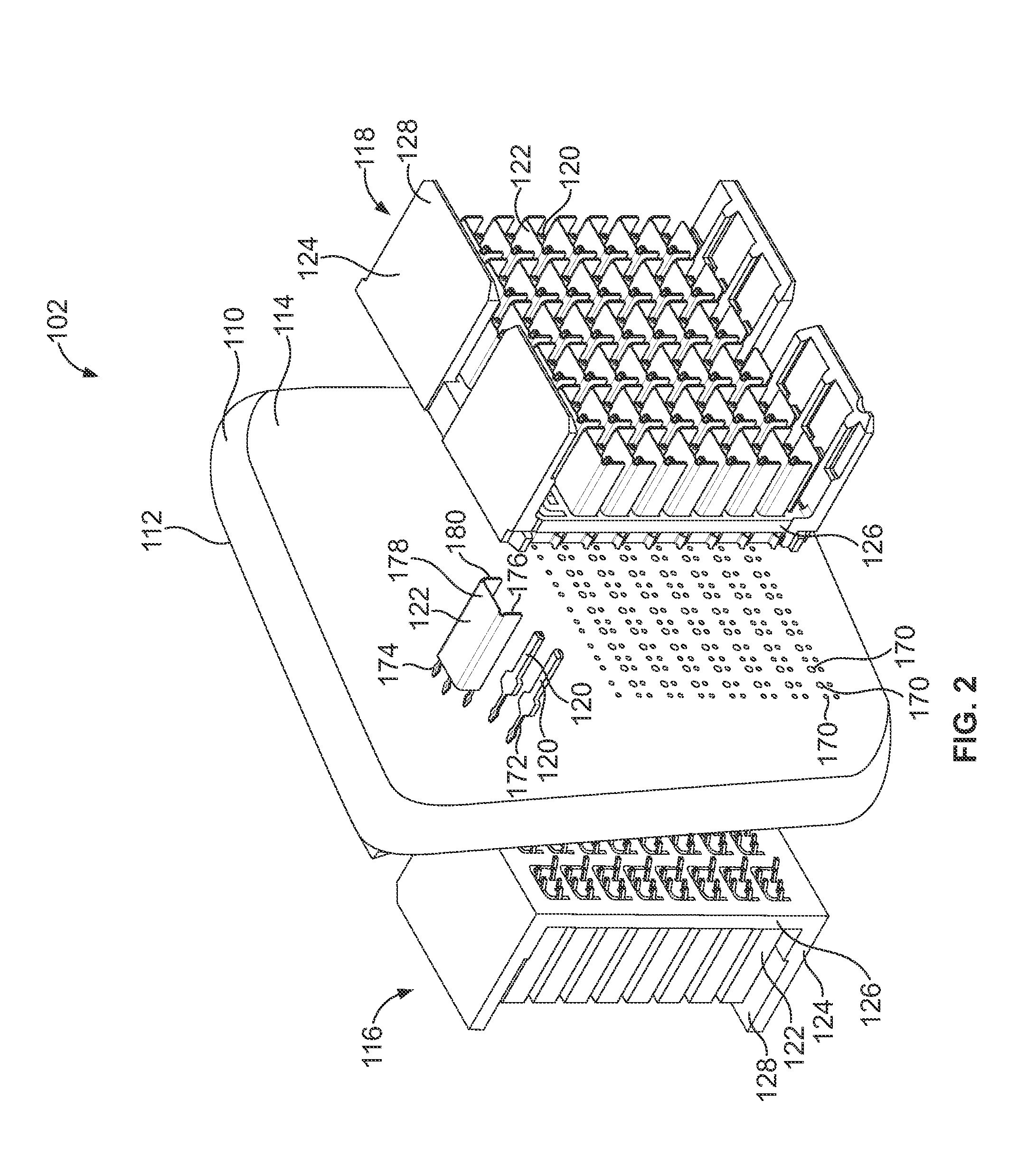
[0020]The midplane assembly 102 includes a midplane circuit board 110 having a first side 112 and second side 114. The midplane assembly 102 includes a first header assembly 116 mounted to and extending from the first side 112 of the midplane circuit b...


PUM


Abstract

A receptacle assembly for a midplane connector system has a receptacle housing having openings receiving signal contacts and ground shields of a header assembly. The receptacle assembly includes contact modules coupled to the receptacle housing that each have a leadframe, a dielectric frame and a ground shield. The leadframe has signal contacts arranged in pairs carrying differential signals that are generally arranged along a leadframe plane with mating portions at ends thereof that have at least two points of contact electrically connected to a corresponding signal contact of the header assembly. The dielectric frame holds the signal contacts. The ground shield is coupled to a side of the dielectric frame and has ground tabs extending into the dielectric frame to provide electrical shielding between the pairs of signal contacts and grounding beams electrically connected to ground shields of the header assembly.

Description

BACKGROUND OF THE INVENTION[0001]The subject matter herein relates generally to electrical connectors for use in a midplane connector system.[0002]Some electrical systems, such as network switches and computer servers with switching capability, include receptacle connectors that are oriented orthogonally on opposite sides of a midplane in a cross-connect application. Switch cards may be connected on one side of the midplane and line cards may be connected on the other side of the midplane. The line card and switch card are joined through header connectors that are mounted on opposite sides of the midplane board. Typically, traces are provided on the sides and / or the layers of the midplane board to route the signals between the header connectors. Sometimes the line card and switch card are joined through header connectors that are mounted on the midplane in an orthogonal relation to one another. The connectors include patterns of signal and ground contacts that extend through a patte...

Claims


Application Information

Patent Timeline
Patent Type & Authority Applications(United States)
IPC IPC(8): H01R12/00H01R13/648
CPCH01R12/7082H01R12/716H01R12/737H01R13/65807H05K2201/10295H05K1/141H05K3/366H05K2201/044H01R13/6587
Inventor DAVIS, WAYNE SAMUELWHITEMAN, JR., ROBERT NEIL
Owner TYCO ELECTRONICS LOGISTICS AG (CH)
Why Eureka
Try Eureka