Assembly apparatus for bearing assembly

Inactive Publication Date: 2013-08-22
HONG FU JIN PRECISION IND (SHENZHEN) CO LTD +1
View PDF4 Cites 6 Cited by
  • Summary
  • Abstract
  • Description
  • Claims
  • Application Information

AI Technical Summary

Problems solved by technology

Such an assembly process is complicated, and has a low efficiency.
In addition, the b

Method used


Image

  • Assembly apparatus for bearing assembly
  • Assembly apparatus for bearing assembly
  • Assembly apparatus for bearing assembly

Examples


Embodiment Construction

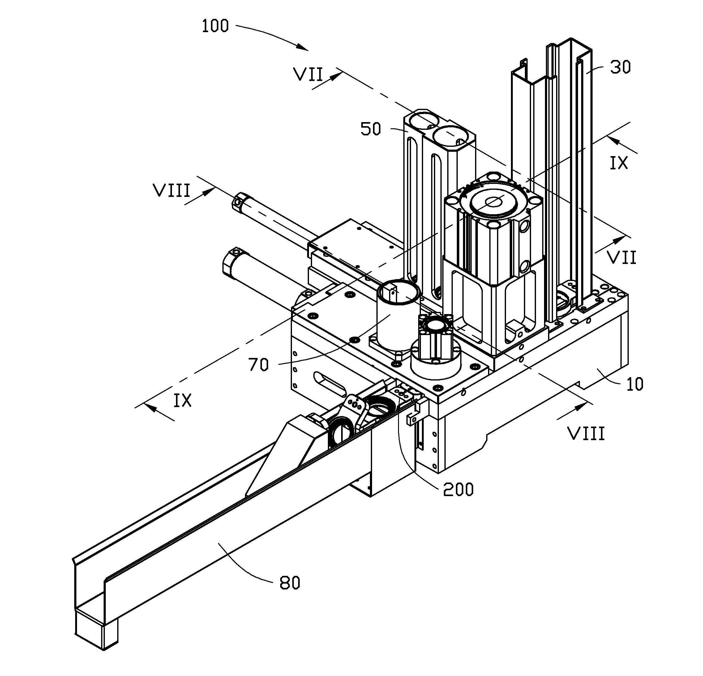
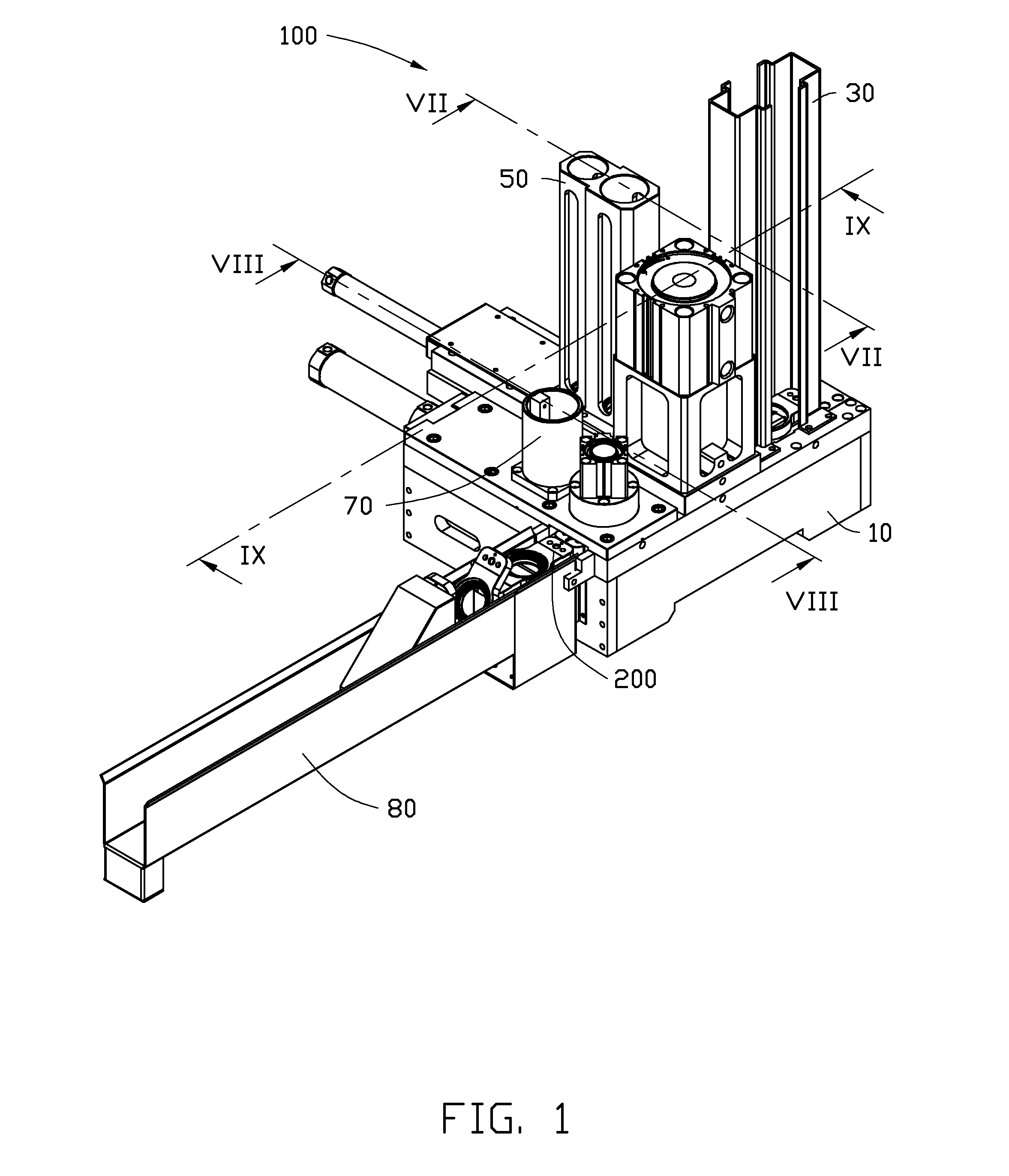
[0015]FIG. 1 shows an embodiment of an assembly apparatus 100 used for assembling a bearing assembly 200 (shown in FIG. 2). The bearing assembly 200 includes a bearing seat 201, a bearing 203, a bushing 205, and a latching ring 207. The bearing seat 201 includes a base portion 2011 and a guiding portion 2013 extending from opposite sides of the base portion 2011. The base portion 2011 is substantially circular, and defines a mounting hole 2015 in a center position thereof. A flange 2017 is formed on an inside surface of the mounting hole 2015. A latching groove 2019 is defined in the inside surface of the mounting hole 2015, for receiving the latching ring 207. The bearing 203 defines a shaft hole 2031. An inner diameter of the shaft hole 2031 is substantially the same as an outer diameter of the bushing 205, such that the bearing 203 is sleeved on the bushing 205. The bushing 205 installed with the bearing 203 is mounted in the mounting hole 2015 of the bearing seat 201, and is sup...


PUM


Abstract

An assembly apparatus for automatically assembling a bearing assembly includes a base, a transferring mechanism, a first assembly mechanism, and a second assembly mechanism. The transferring mechanism is movably mounted on the base, for transferring and positioning the bearing seat. The first assembly mechanism is mounted on the base adjacent to the transferring mechanism, for installing the bearing and the bushing into the mounting hole of the base. The second assembly mechanism is mounted on the base adjacent to the first assembly mechanism, for installing the latching ring into the latching groove of the bearing seat.

Description

BACKGROUND[0001]1. Technical Field[0002]The present disclosure relates to assembly apparatuses, and particularly to an assembly apparatus for bearing assembly.[0003]2. Description of Related Art[0004]A bearing assembly generally includes a bearing seat, a bearing, a bushing, and a latching ring. During an assembly process, the bearing and the bushing are manually positioned on a same straight line, and then the bushing is inserted into the bearing by an external mechanical force; the bearing installed with the bushing is manually mounted in a mounting hole of the bearing seat; and lastly, the latching ring is manually sleeved on the bearing, for latching the bearing in the bearing seat. Such an assembly process is complicated, and has a low efficiency. In addition, the bearing contacts with the hands of the operator, so that the bearing may rust easily.[0005]Therefore, there is room for improvement in the art.BRIEF DESCRIPTION OF THE DRAWINGS[0006]The components in the drawings are ...

Claims


Application Information

Patent Timeline
IPC IPC(8): F16C43/02
CPCF16C43/02F16C2226/74F16C2300/02Y10T29/53796F16C35/067F16C35/073B23P19/04F16C35/045
Inventor LIU, JUNZHANG, CHUN-MING
Owner HONG FU JIN PRECISION IND (SHENZHEN) CO LTD
Why Eureka
Try Eureka