
Laundry treating machine

a technology for treating machines and laundry, which is applied in drying machines, washing machines with receptacles, lighting and heating apparatus, etc. it can solve problems such as wasting cooling water, reducing the efficiency of condensing ducts, and fan out of order, so as to improve condensing efficiency

Active Publication Date: 2013-08-22
LG ELECTRONICS INC
View PDF5 Cites 31 Cited by
  • Summary
  • Abstract
  • Description
  • Claims
  • Application Information

AI Technical Summary

Benefits of technology

The present invention aims to improve the efficiency of a laundry treating machine by improving the condensing structure that removes moisture from heated air with dried laundry. Additionally, the invention provides an improved repair and maintenance structure for the lint filter that filters lint from heated air. The invention includes a plurality of nozzles that spray cleaning water at a slant to widen the spread of the cleaning water in the width direction of the lint filter. The filter frame also includes a reflective plate to shield a portion of the filter to prevent the cleaning water from entering the tub. These improvements enhance the performance of the laundry treating machine.

Problems solved by technology

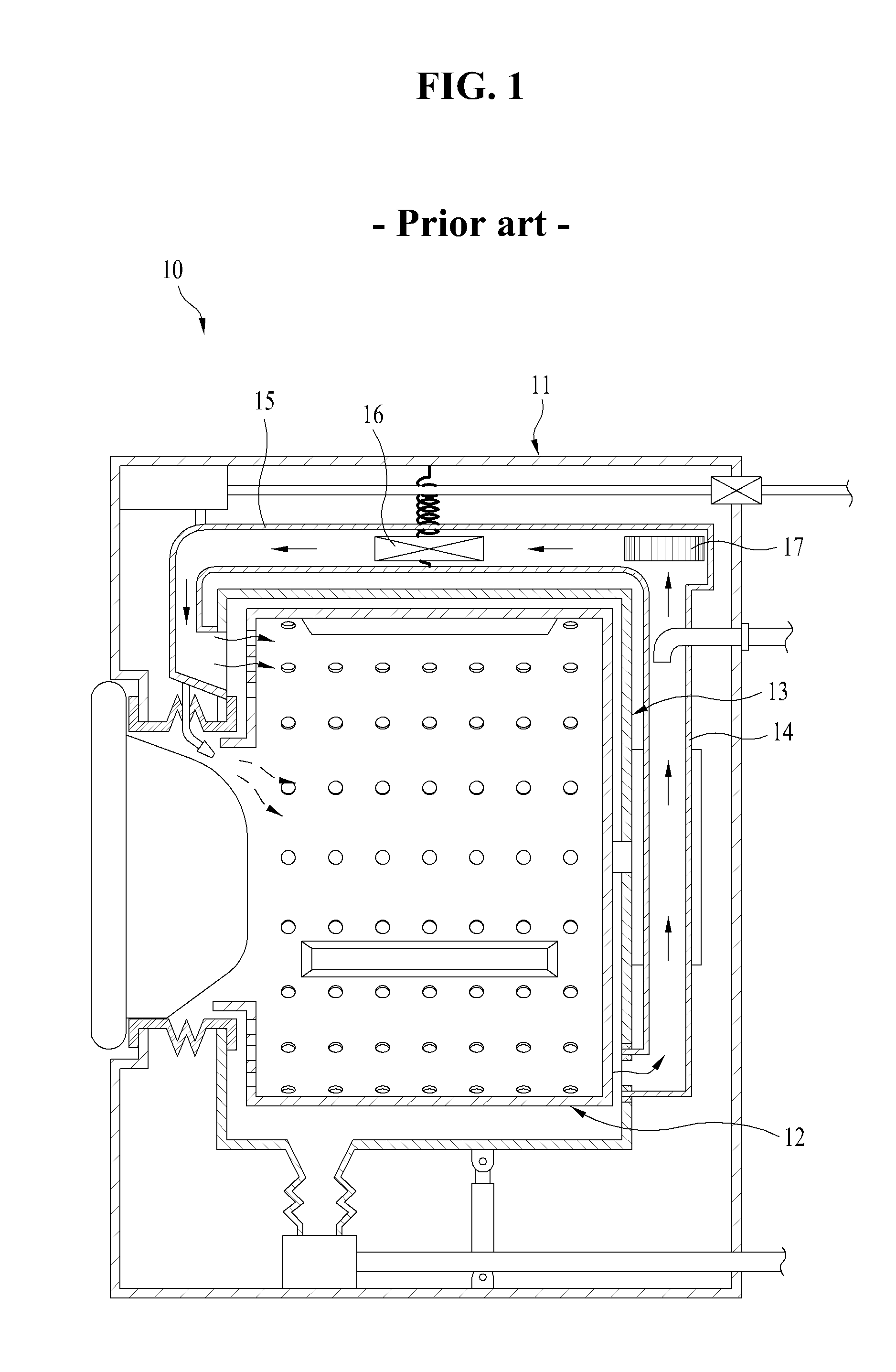
In order to condense moisture contained in the wet air being introduced to the condensing duct in the steps, it is required to keep supplying a high flow rate of cooling water in the course of drying the laundry, which causes a problem of wasting of the cooling water.
Consequently, the lint remaining at the condensing duct 14 is liable to reduce efficiency of the condensing duct, the lint remaining at the condensing duct 14 is liable to make the fan to go out of order, and the lint remaining at the heating duct 15 is liable to make the heater 16 provided to the heating duct 15 to go out of order, or cause breaking out of fire.

Method used


Image

  • Laundry treating machine
  • Laundry treating machine
  • Laundry treating machine

Examples


Embodiment Construction

[0050]Reference will now be made in detail to the specific embodiments of the present invention, examples of which are illustrated in the accompanying drawings. Wherever possible, the same reference numbers will be used throughout the drawings to refer to the same or like parts.

[0051]In describing the present invention, terms of elements defined herein have been defined taking functions thereof in the present invention into account. Therefore, it is required that the terms are not to be understood in a sense that the terms limit technical elements of the present invention. And, the terms of the elements defined thus may be called in other terms in this field of art.

[0052]A laundry treating machine in accordance with a preferred embodiment of the present invention will be described with reference to the attached drawings, in detail.

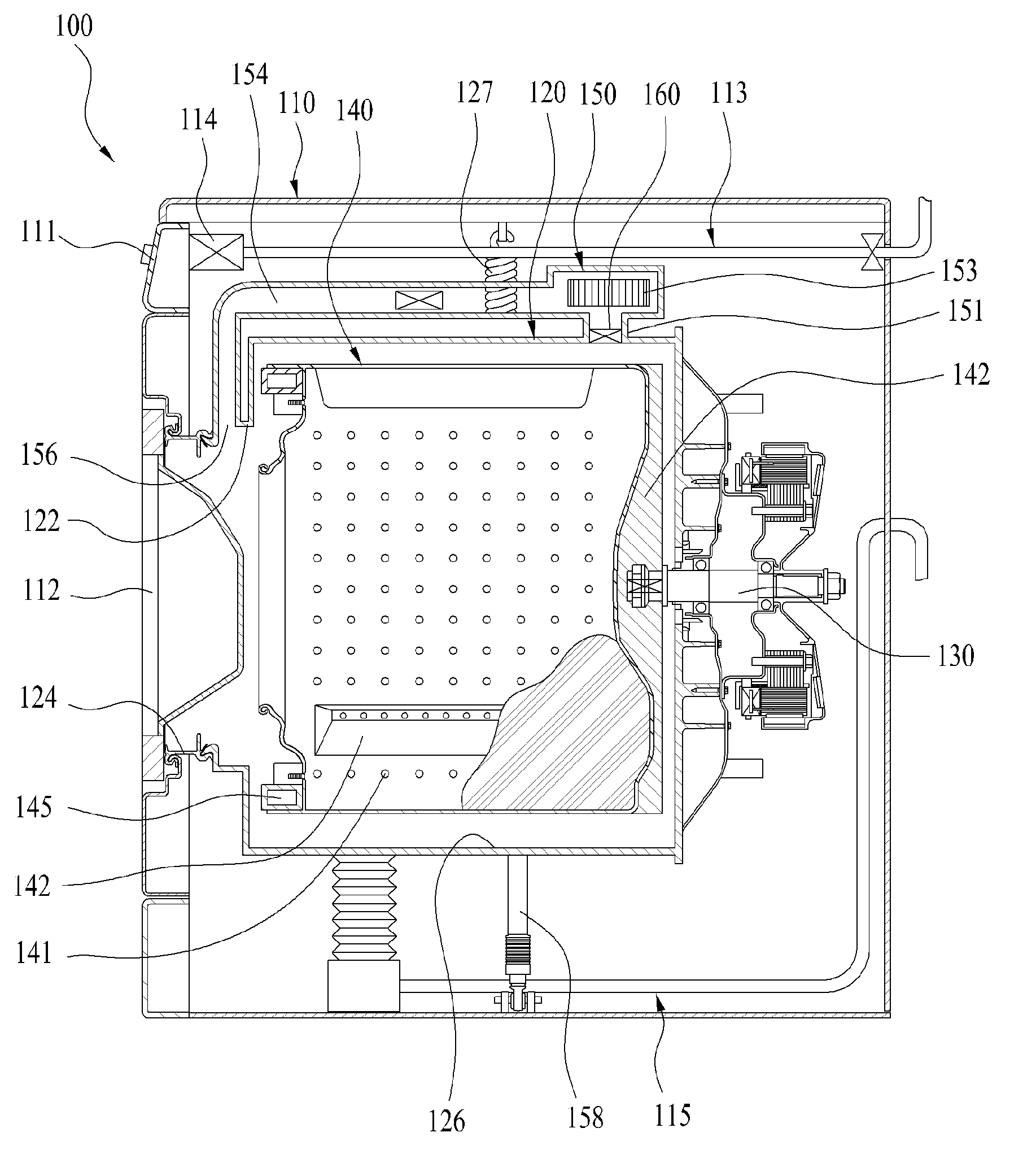
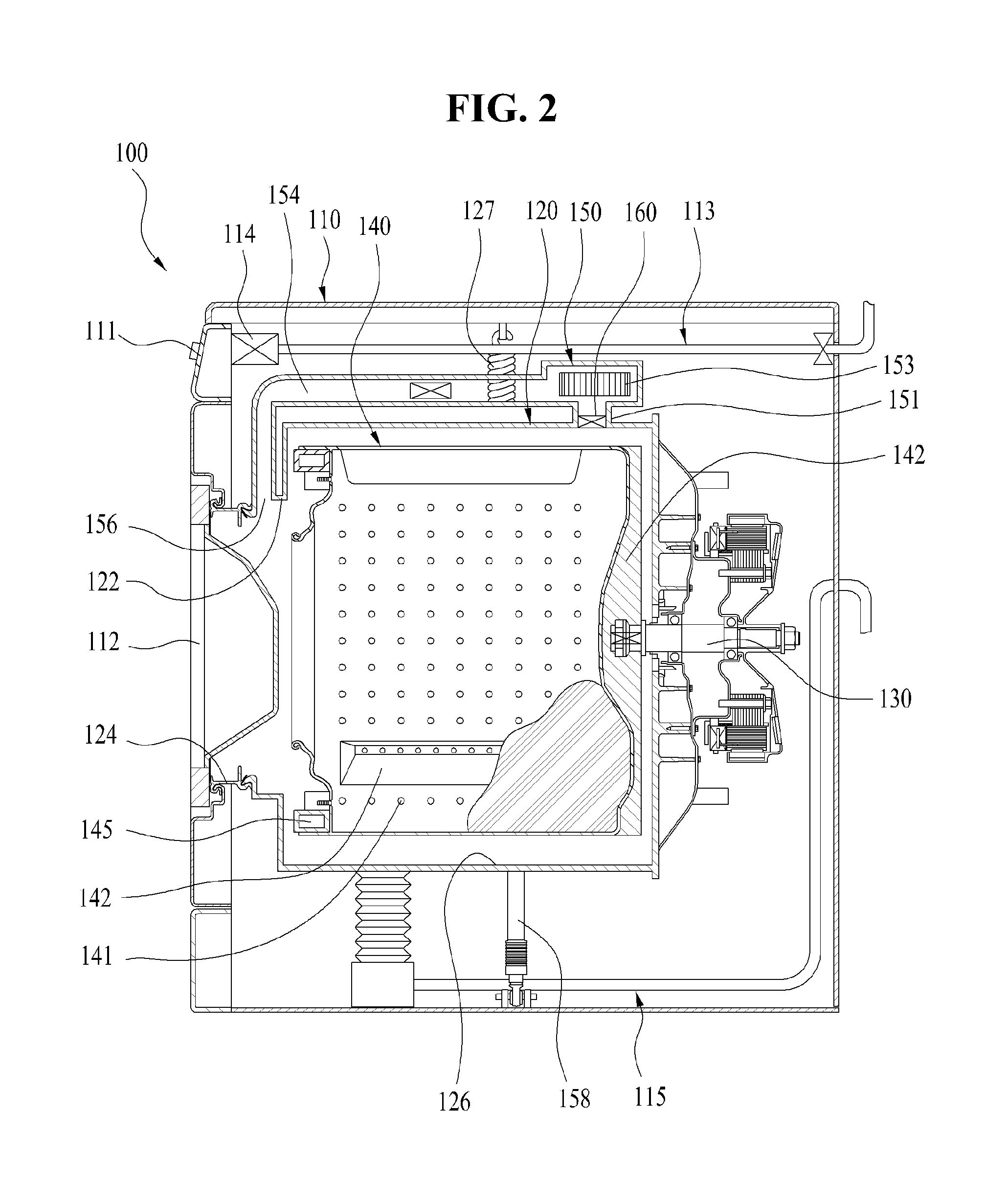
[0053]FIG. 2 illustrates a schematic view of an inside structure of a laundry treating machine of the present invention, and FIG. 3 illustrates a perspect...


PUM


Abstract

The present invention relates to a laundry treating machine, and more particularly, a laundry treating machine including an air supply unit for supplying air, a tub for having the air supplied thereto from the air supply unit to treat the laundry, the tub having an air recovery opening formed in an outside circumferential surface thereof for recovery of the air to the air supply unit, a lint filter mounted to an inside of the air recovery opening for filtering the lint from the air, and a filter cleaning unit for spraying cleaning water toward the lint filter to separate the lint from the lint filter, wherein the filter cleaning unit is extended and branched to the inside of the air recovery opening for spraying the cleaning water to the lint filter.

Description

CROSS REFERENCE TO RELATED APPLICATION[0001]This application claims the benefit of the Patent Korean Application No. 10-2012-0017878, filed on Feb. 22, 2012, which is hereby incorporated by reference as if fully set forth herein.BACKGROUND OF THE DISCLOSURE[0002]1. Field of the Disclosure[0003]The present invention relates to laundry treating machines, and more particularly, to a laundry treating machine which is made to clean a lint filter provided for filtering lint produced when laundry is being dried.[0004]2. Discussion of the Related Art[0005]In general, as examples of the laundry treating machine, there are washing machines, and drying and washing machines. The washing machine is a product for removing different kinds of dirt from clothes and beddings by using a softening action of detergent and a friction and an impact to the laundry of a water circulation caused by a pulsator or a drum. A full automatic washing machine appeared recently progresses a series of strokes of a wa...

Claims


Application Information

Patent Timeline
IPC IPC(8): F26B21/00
CPCF26B21/003D06F25/00D06F58/22D06F39/088D06F58/24D06F39/10D06F58/10D06F58/04Y02B40/00
Inventor KIM, HYOJUNKIM, WOORELEE, JUNGHOON
Owner LG ELECTRONICS INC
Learn More