High mass flow check valve aspirator

a technology of check valve aspirator and high mass flow, which is applied in the field of check valves, can solve problems such as boosting vacuum

Active Publication Date: 2013-08-22
TECHNIPLAS US LLC
View PDF11 Cites 79 Cited by
  • Summary
  • Abstract
  • Description
  • Claims
  • Application Information

AI Technical Summary

Problems solved by technology

While such designs work well, modern engine specifications often demand higher boosted vacuum flow and quicker vacuum recovery from the vacuum booster subsystems.

Method used


Image

  • High mass flow check valve aspirator
  • High mass flow check valve aspirator
  • High mass flow check valve aspirator

Examples


Embodiment Construction

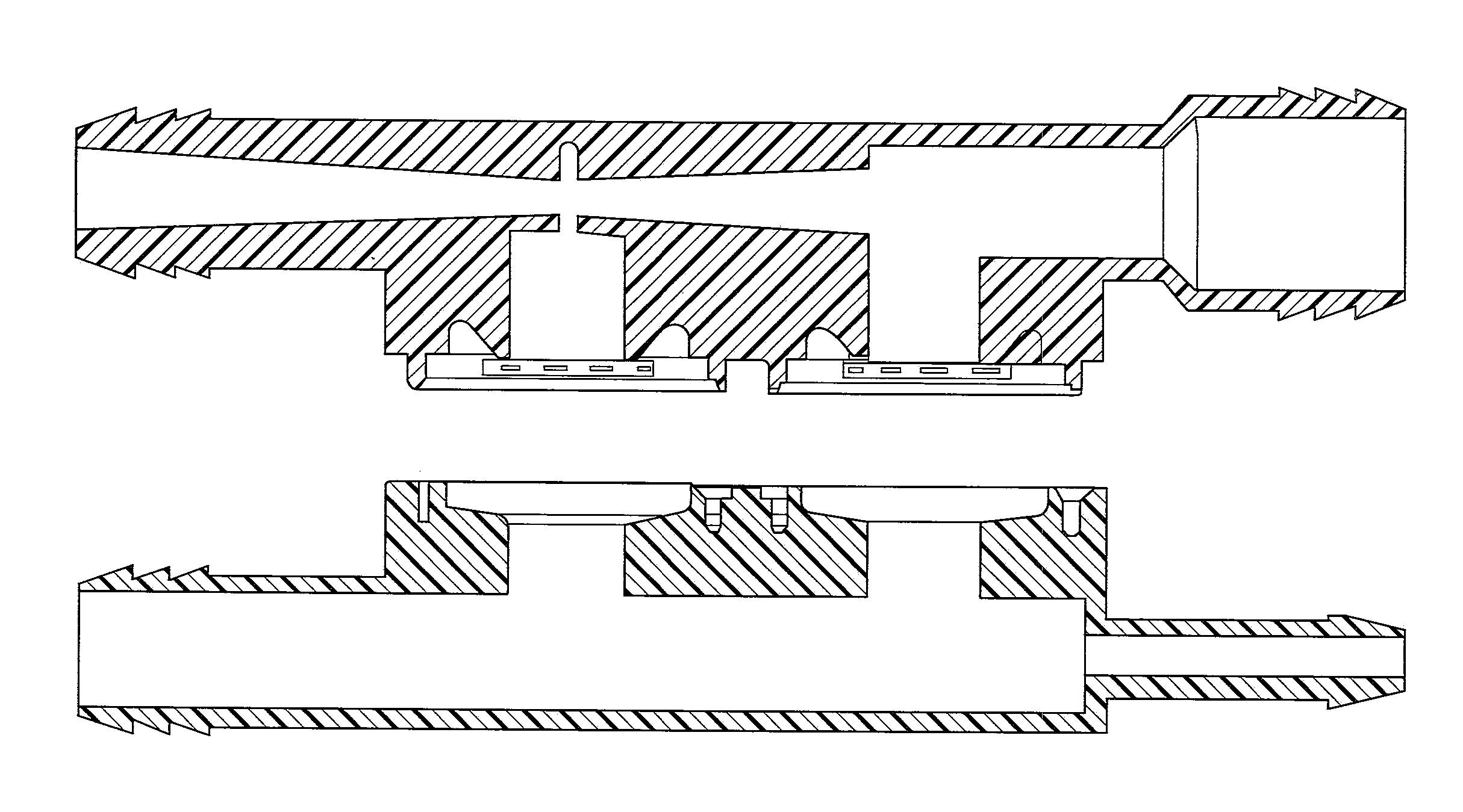
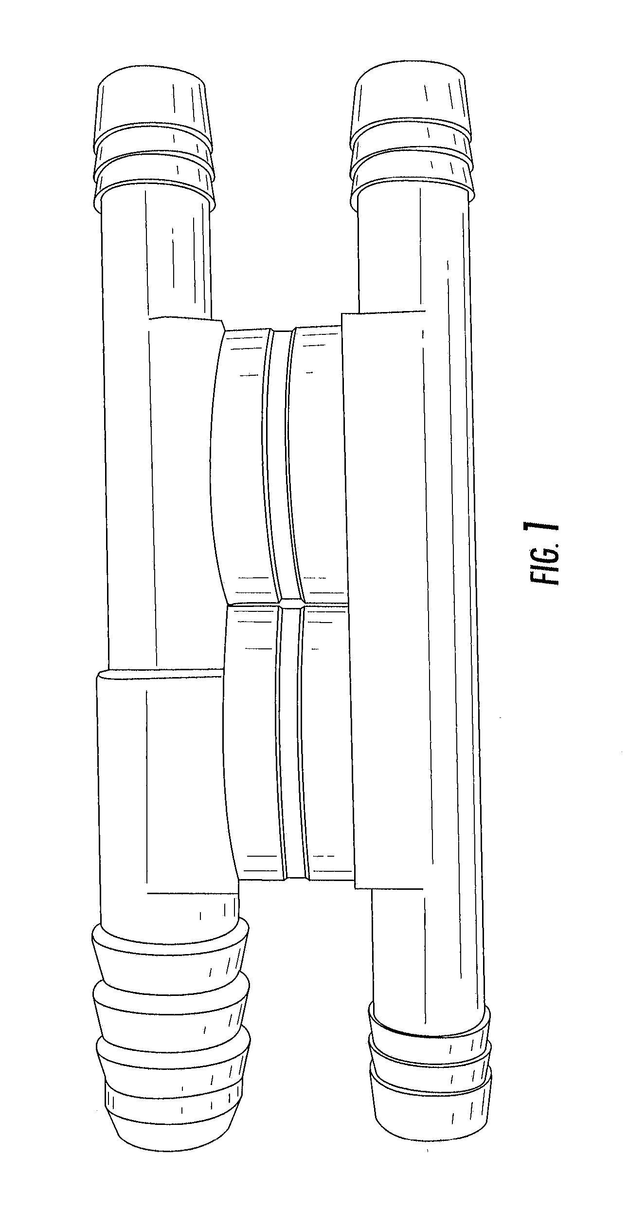
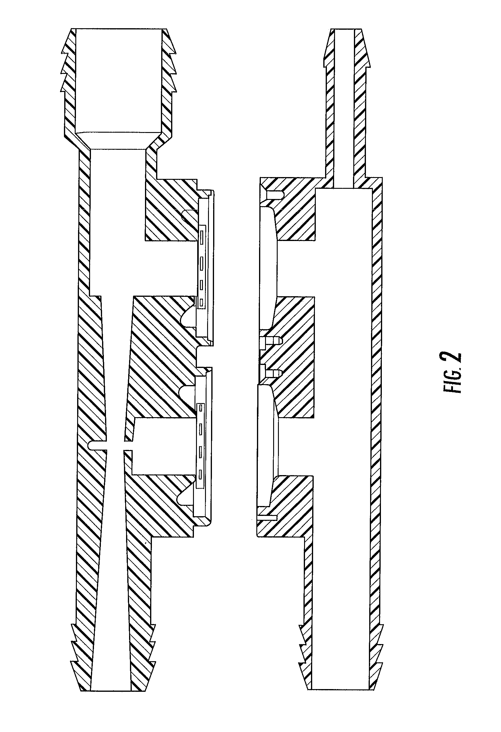
[0006]The embodiments disclosed herein provide a check valve aspirator including a venturi pipe having a converging section with a converging inlet and a converging outlet, and a diverging section with a diverging inlet and a diverging outlet. The converging outlet is in fluid communication with the diverging inlet. An outlet channel is in fluid communication with the venturi pipe and has an outlet port. A ratio of a diameter of the converging section outlet to a diameter of the outlet port is less than 0.4. In one embodiment, the ratio of the diameter of the converging section outlet to the diameter of the outlet port is within a range of 0.3 to 0.35. In another embodiment, a ratio of the diameter of the converging section outlet to a diameter of the diverging section inlet is at least 0.8. In yet another embodiment, a ratio of a diameter of the converging section inlet to the diameter of the converging section outlet is less than 3.5. The ratio of the diameter of the converging se...


PUM


Abstract

The embodiments disclosed herein provide a check valve aspirator including a venturi pipe having a converging section with a converging inlet and a converging outlet, and a diverging section with a diverging inlet and a diverging outlet. The converging outlet is in fluid communication with the diverging inlet. An outlet channel is in fluid communication with the venturi pipe and has an outlet port. A ratio of a diameter of the converging section outlet to a diameter of the outlet port is less than 0.4.

Description

CROSS-REFERENCE TO RELATED APPLICATIONS[0001]The present application claims priority to U.S. Provisional Patent Application No. 61 / 600880 filed Feb. 20, 2012 and titled “HIGH MASS FLOW CHECK VALVE ASPIRATOR”, which is herein incorporated by reference in its entirety.TECHNICAL FIELD OF THE DISCLOSED EMBODIMENTS[0002]The present invention generally relates to check valves and, more particularly, to high mass flow check valve aspirators.BACKGROUND OF THE DISCLOSED EMBODIMENTS[0003]Internal combustion engines have long employed air flow conduits to provide vacuum assist for automobile subsystems, such as brakes; automatic transmissions and others. These systems often employed check valves located along the air flow conduit to prevent subsystem back pressure from reaching the engine, a typical check valve of this sort is described in U.S. Pat. No. 3,889,710.[0004]These designs were improved upon with a check valve of the type disclosed in U.S. Pat. No. 5,291,916, which provided for a spa...

Claims


Application Information

Patent Timeline
Patent Type & Authority Applications(United States)
IPC IPC(8): F16K15/14
CPCF16K15/14B60T17/04B60T17/02Y10T137/87587
Inventor BURNHAM, MATTHEWSMITH, ANDYBACKHUS, AMY
Owner TECHNIPLAS US LLC
Why Eureka
Try Eureka