Convective Airflow Using a Passive Radiator

a passive radiator and convective technology, applied in the direction of electrical transducers, transducer details, lighting and heating apparatus, etc., can solve the problems of reducing speaker performance and durability, introducing additional heat, and fan components in such devices can consume power, space, and consume additional heat, so as to increase the amount of heat removed, strengthen the structural integrity of the enclosure, and increase the effect of heat production

Active Publication Date: 2013-08-22
BOSE CORP
View PDF6 Cites 29 Cited by
  • Summary
  • Abstract
  • Description
  • Claims
  • Application Information

AI Technical Summary

Benefits of technology

[0006]According to another particular embodiment, movement of a passive radiator initiates airflow that removes heat from the structure and the enclosure. The passive radiator further draws in cooler, ambient air to absorb additional heat from the structure. A frame securing the passive radiator and the structure in a fixed relationship additio...

Problems solved by technology

Smaller spacing requirements in a speaker system can present heat dissipation challenges.
For example, an energized voice coil of an acoustic transducer generates heat that can reduce s...

Method used


Image

  • Convective Airflow Using a Passive Radiator
  • Convective Airflow Using a Passive Radiator
  • Convective Airflow Using a Passive Radiator

Examples


Embodiment Construction

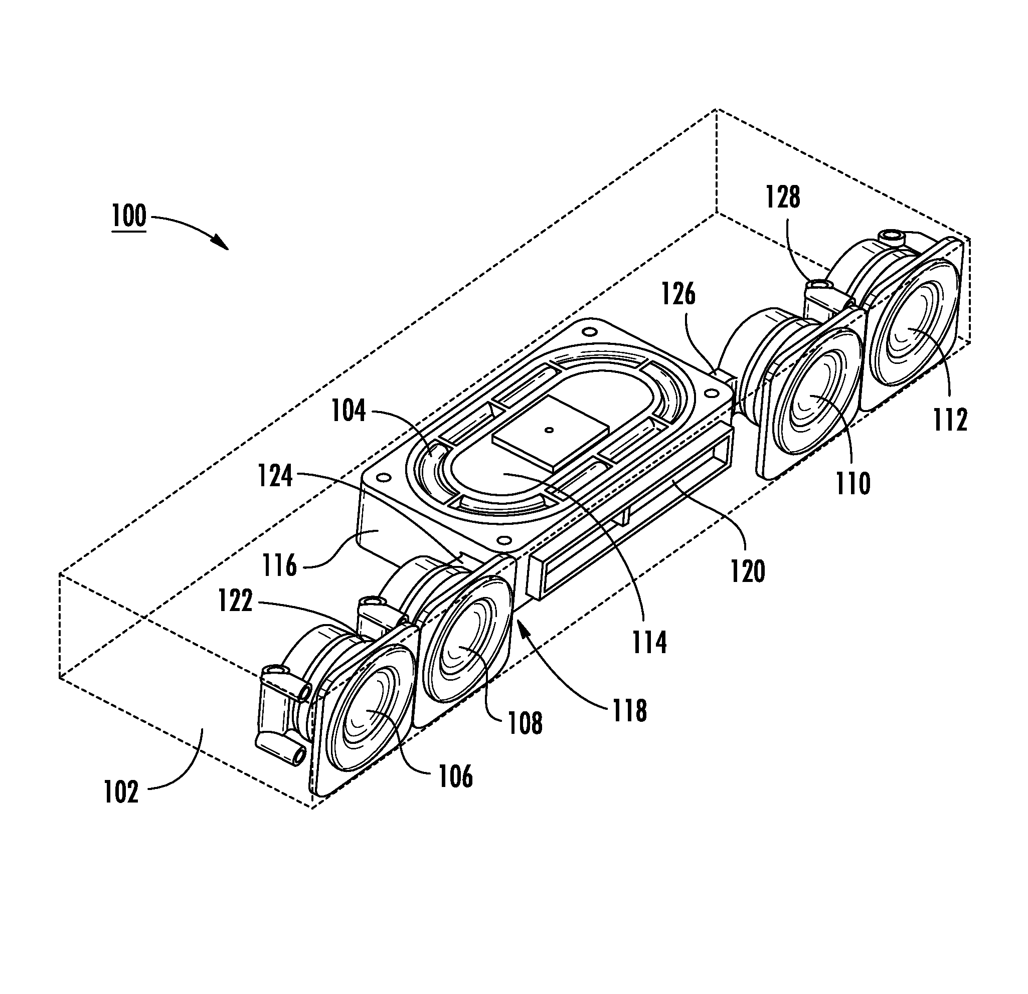
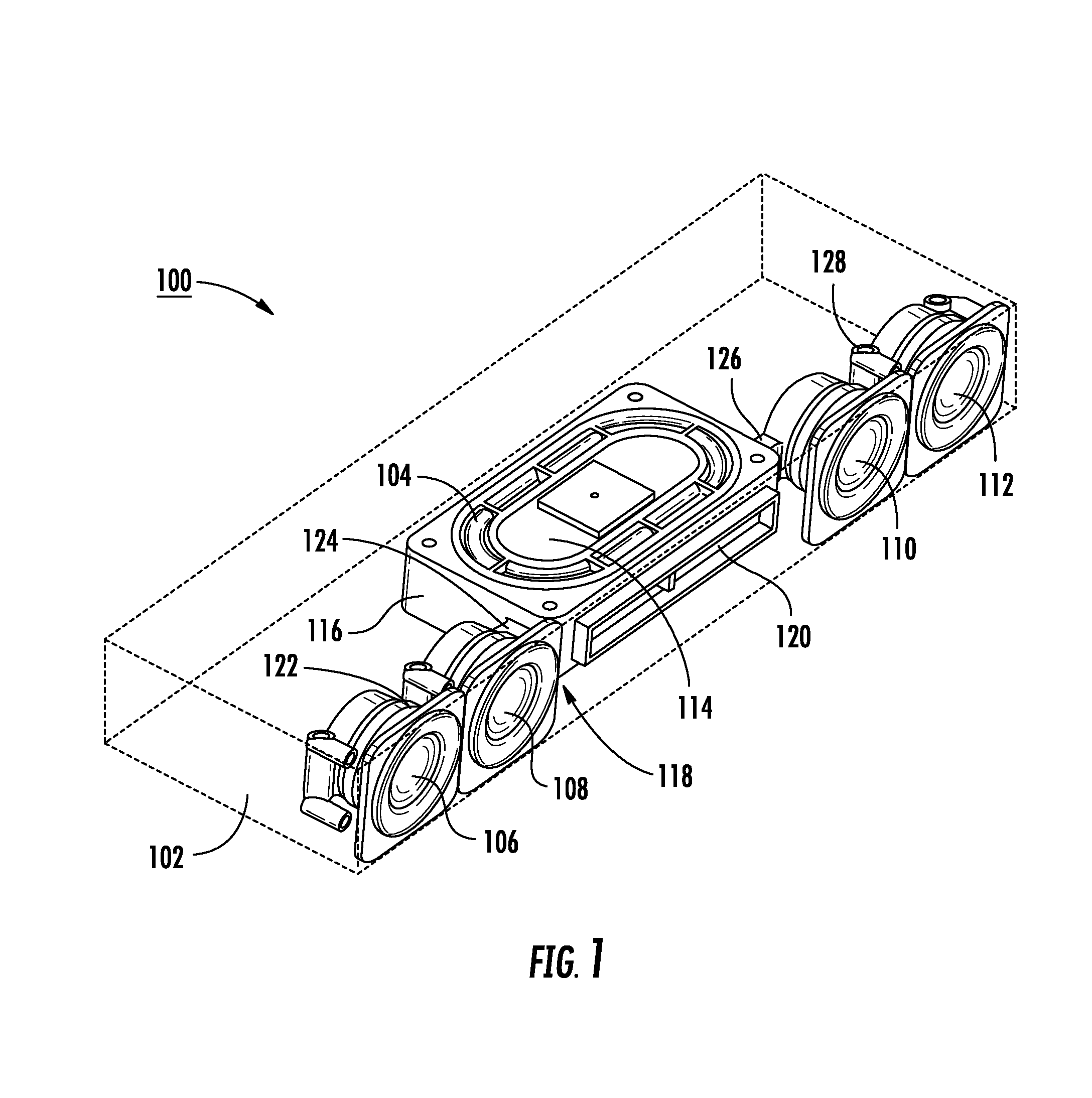
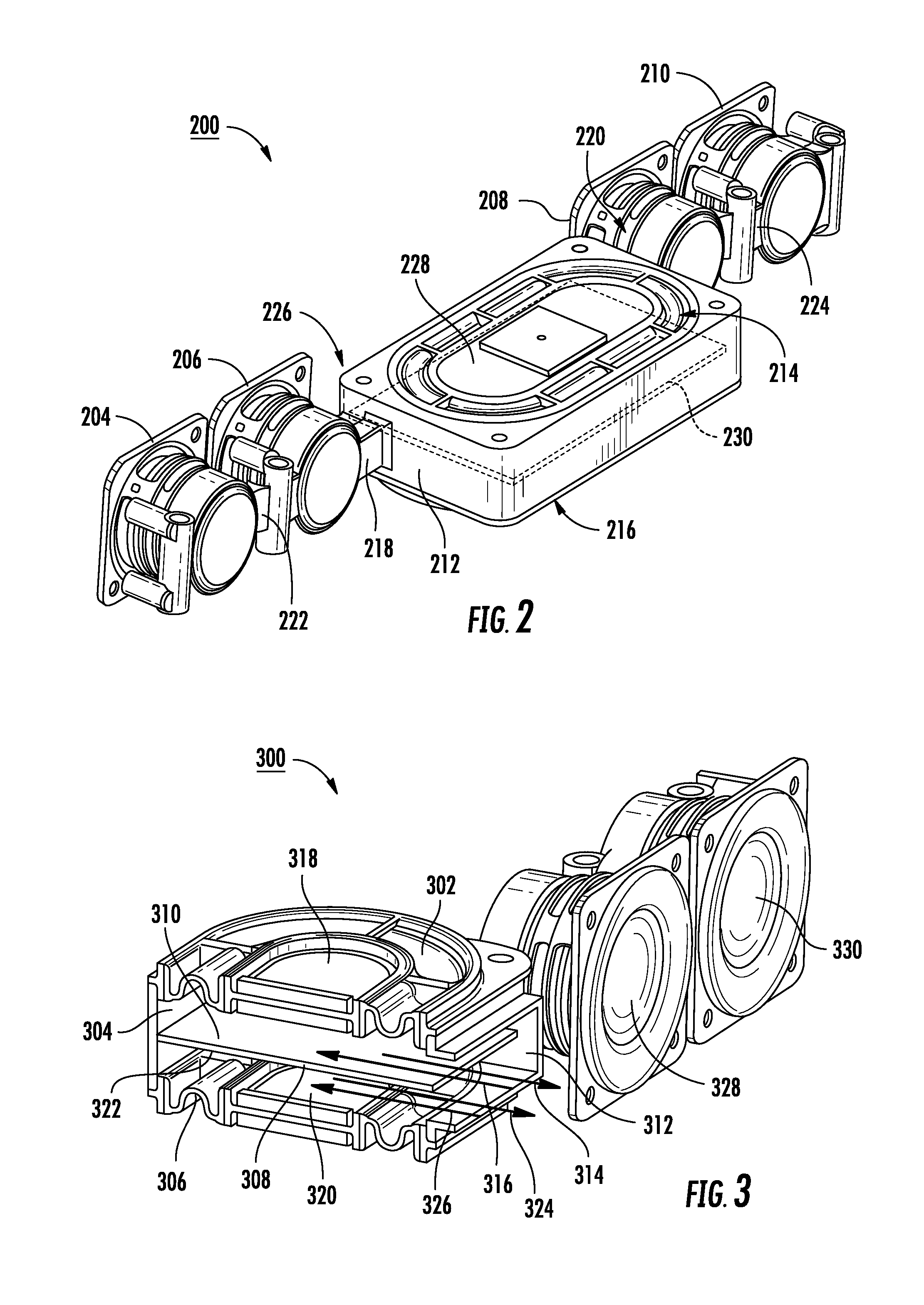
[0014]In a particular embodiment, an apparatus uses a passive radiator to create airflow that removes heat from an acoustic enclosure. A diaphragm of the passive radiator moves in response to air pressure changes within the acoustic enclosure. A thermally conductive structure extends over at least a portion of the passive radiator. The structure is coupled via a low thermal resistance thermally conductive path to one or more heat sources located within or coupled to the enclosure. Air accelerated by motion of the diaphragm flows over and conducts heat away from the structure and out of the acoustic enclosure. A frame secures the passive radiator and the structure in a fixed relationship, or the passive radiator is directly affixed to the structure.

[0015]Changes in air pressure within the enclosure are caused by motion of the diaphragm of an acoustic transducer coupled to the acoustic enclosure. The air pressure variations inside the acoustic enclosure, in turn, cause the passive rad...


PUM


Abstract

Systems and methods to remove heat from an acoustic enclosure are provided. An apparatus for reproducing acoustic signals includes an acoustic enclosure comprising an acoustic volume. A heat producing element is coupled to the acoustic enclosure, and a thermally conductive structure is thermally coupled to the heat producing element. The thermally conductive structure includes a first surface. A first passive radiator includes a first diaphragm. The first diaphragm extends over at least a portion of the first surface and moves in response to pressure variations within the acoustic volume. Movement of the first diaphragm causes air to flow over the first surface, to facilitate heat removal from the thermally conductive structure.

Description

I. FIELD OF THE DISCLOSURE[0001]The disclosure relates to heat removal in acoustic devices, and more particularly, to heat removal from acoustic enclosures.II. BACKGROUND[0002]To satisfy user demands for convenience and practicality, speaker systems are designed to be light and small. Smaller spacing requirements in a speaker system can present heat dissipation challenges. For example, an energized voice coil of an acoustic transducer generates heat that can reduce speaker performance and durability. While forced air convection devices are helpful in dissipating heat, fan components in such devices can consume power, space, and introduce additional heat.III. SUMMARY OF THE DISCLOSURE[0003]In a particular embodiment, an apparatus for reproducing acoustic signals includes an acoustic enclosure comprising an acoustic volume. A heat producing element is coupled to the acoustic enclosure, and a structure is thermally coupled to the heat producing element. The structure includes a first s...

Claims


Application Information

Patent Timeline
IPC IPC(8): H04R1/02F28F7/00
CPCH04R1/2834
Inventor LITOVSKY, ROMAN N.WILLIAMS, CHESTER SMITH
Owner BOSE CORP
Why Eureka
Try Eureka