
Ball valve enclosure and drive mechanism

a technology of drive mechanism and ball valve, which is applied in the direction of engine components, mechanical equipment, and wellbore/well accessories, etc., can solve the problems of valve inoperableness, ball valves in high stress applications can be more susceptible to problems, and the ball valve can stall before the end of its intended life cycle, so as to improve the support of the ball and improve the guidance

Active Publication Date: 2013-08-22
VETCO GRAY
View PDF13 Cites 2 Cited by
  • Summary
  • Abstract
  • Description
  • Claims
  • Application Information

AI Technical Summary

Benefits of technology

This patent is about a ball valve assembly that has a split enclosure around the ball, allowing for better support and guidance during rotation. The assembly also has top and bottom seats, and locking profiles that engage corresponding flanges on the seats. Actuation arms are attached to a cross-head through a double taper profile, which converts piston force into rotational force. The design also provides optimal clearance between the enclosure and the ball to prevent solid contamination from affecting ball rotation. The actuation arm dual taper profile compensates for a radial force created by the piston force during a stalled ball condition. A unique profile is made in the actuation arm to support the link arm and accommodate its path during ball rotation. An alignment ring is used to ensure proper alignment of the ball passage with the flow path. The alignment can be done by machining the ring before final assembly. The technical effects include increased support and guidance for the ball, improved operational performance, and enhanced durability and reliability.

Problems solved by technology

Ball valves can stall before the end of their intended life cycles due to debris ingress, contamination formation, corrosion, and lubrication washout.
These events can lead to over stressing and deformation of the mechanism, which can render the valve inoperable.
Ball valves in high stress applications can be more susceptible to problems due to increased torque on the ball valve and the flat trunnion plates which support the ball.

Method used


Image

  • Ball valve enclosure and drive mechanism
  • Ball valve enclosure and drive mechanism
  • Ball valve enclosure and drive mechanism

Examples


Embodiment Construction

[0013]The present invention will now be described more fully hereinafter with reference to the accompanying drawings which illustrate embodiments of the invention. This invention may, however, be embodied in many different forms and should not be construed as limited to the illustrated embodiments set forth herein. Rather, these embodiments are provided so that this disclosure will be thorough and complete, and will fully convey the scope of the invention to those skilled in the art. Like numbers refer to like elements throughout, and the prime notation, if used, indicates similar elements in alternative embodiments.

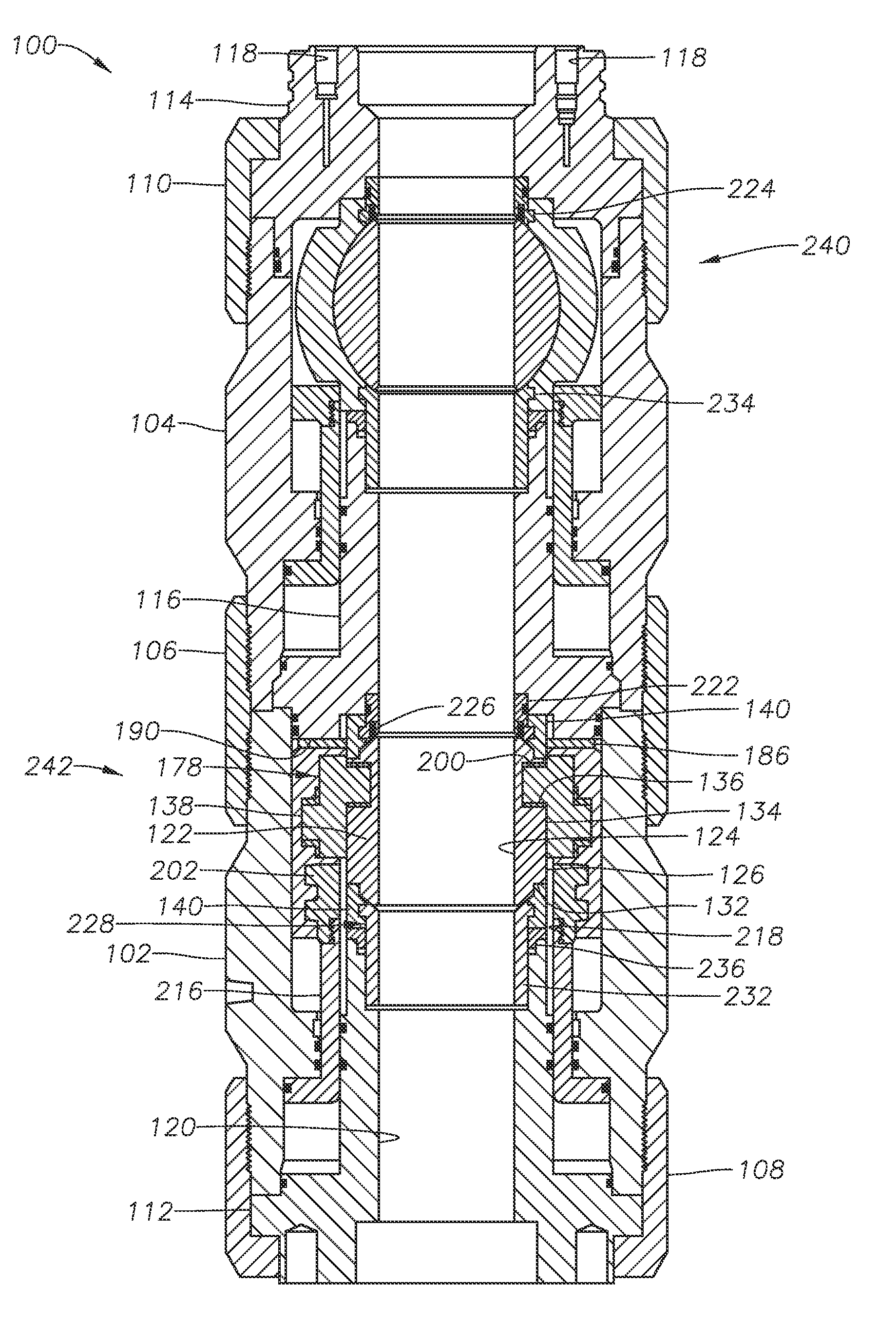
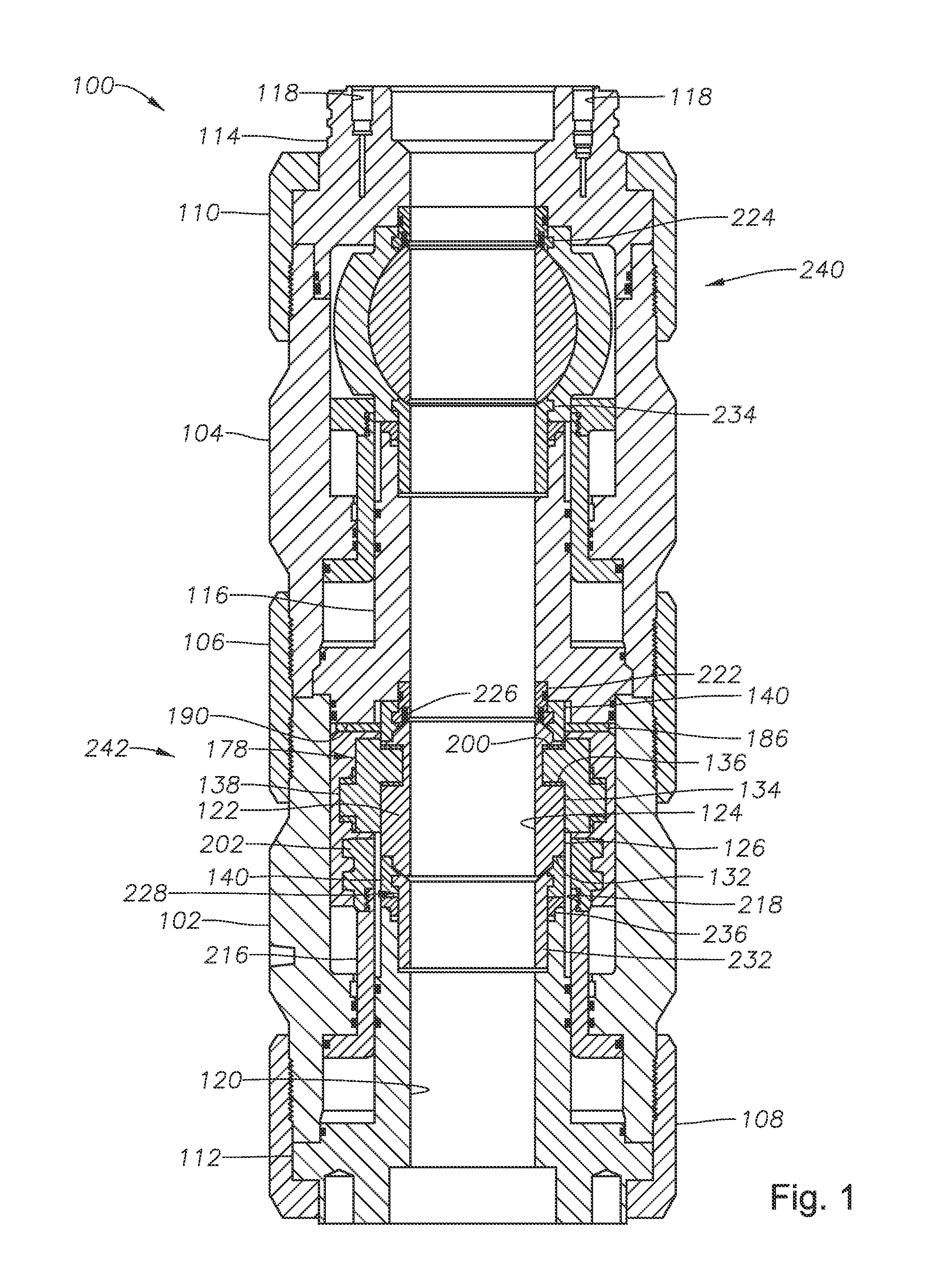
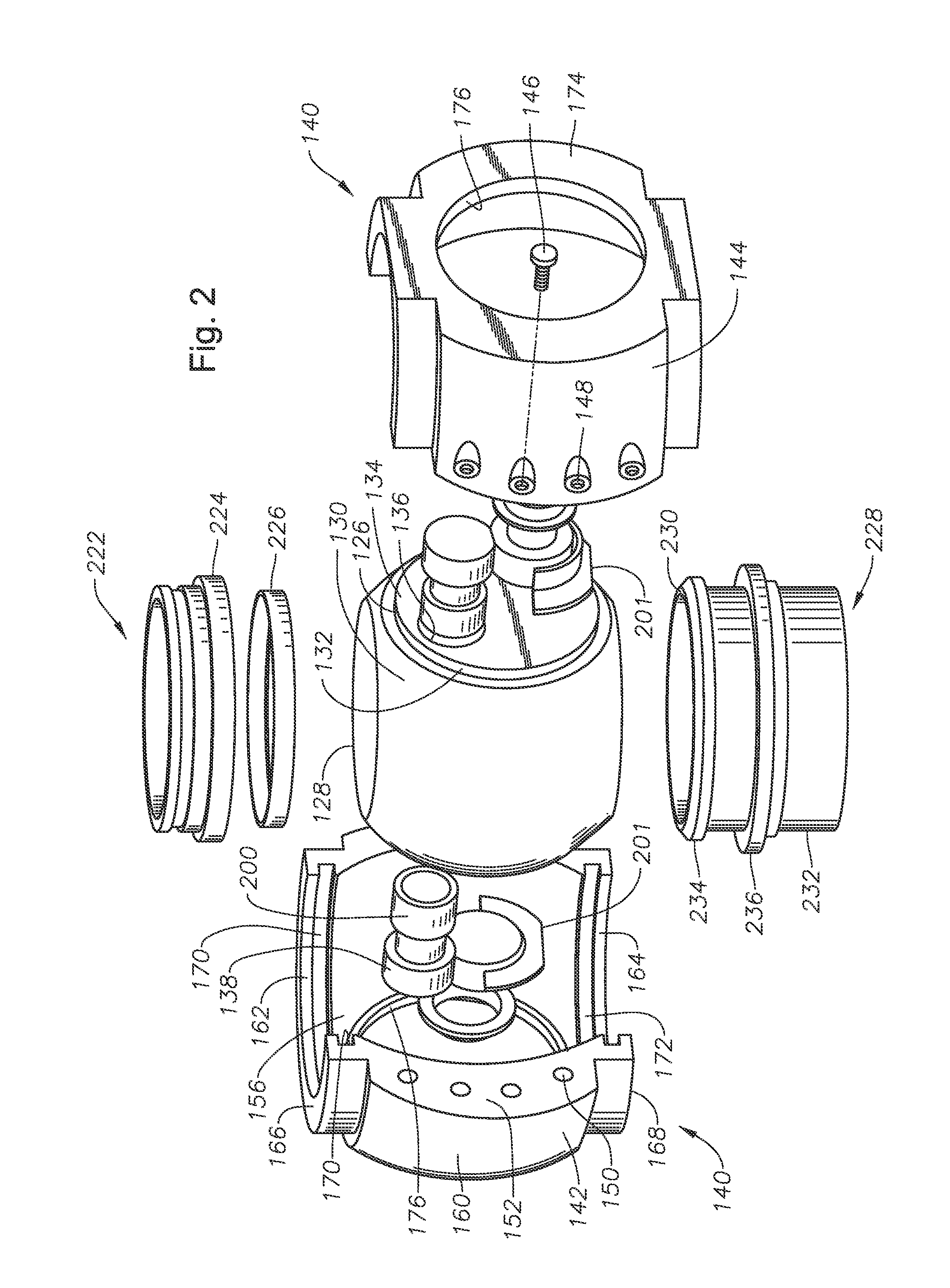
[0014]Referring to FIG. 1, valve assembly 100 can be located in a flowpath such as, for example, in a subsea wellhead. Valve assembly 100 can have an outer housing. In the embodiment shown in FIG. 1, the outer housing can include lower outer housing 102 and upper outer housing 104, which can be joined together by mid locking collar 106. Locking collars, such as lower loc...


PUM


Abstract

A ball valve assembly includes an enclosure for supporting the ball valve during actuation. In one embodiment, the enclosure can be a split enclosure, and can have trunnion support apertures for engaging trunnions on the ball valve. In one embodiment, a pair of link arms are used to transfer force from a pair of actuation members to the ball valve. The link arms can be located in a recess on the actuation members, such the actuation members and the face of the trunnions define a cavity to enclose and protect the link arms.

Description

BACKGROUND OF THE INVENTION[0001]1. Field of the Invention[0002]The present invention relates in general to a ball valve and in particular to a ball valve having an enclosure for reducing deflection during operation.[0003]2. Brief Description of Related Art[0004]The ball of non-floating ball valves typically have trunnions protruding from the sides of the ball. The valve assembly generally includes a trunnion plate for supporting trunnions. Ball valves can stall before the end of their intended life cycles due to debris ingress, contamination formation, corrosion, and lubrication washout. These events can lead to over stressing and deformation of the mechanism, which can render the valve inoperable. Ball valves in high stress applications can be more susceptible to problems due to increased torque on the ball valve and the flat trunnion plates which support the ball.SUMMARY OF THE INVENTION[0005]In one embodiment of a ball valve assembly, a ball valve includes a split type enclosure...

Claims


Application Information

Patent Timeline
Patent Type & Authority Applications(United States)
IPC IPC(8): F16K5/06
CPCF16K5/0647E21B2034/002E21B34/04F16K5/0689E21B2200/04F16K5/0652
Inventor NATARAJAN, SIVAKUMARBUCHAN, ROBERT SAMUELDOMMATI, THIRUPATHI
Owner VETCO GRAY
Learn More