Examining apparatus and method for machine vision system

Inactive Publication Date: 2013-08-22
M VISION
View PDF6 Cites 2 Cited by
  • Summary
  • Abstract
  • Description
  • Claims
  • Application Information

AI Technical Summary

Benefits of technology

The present invention is an examining apparatus for a machine vision system that is easy to access for people with little knowledge of machine vision. It can be quickly and effectively constructed while minimizing expenses. The apparatus uses a public portable terminal such as a smart phone, which makes it easy for people to take pictures of an examination object and start manufacturing a machine vision system without visiting the consumer in person. The invention also provides a database of photographing condition information, which can be used to select an optimal provider among a plurality of providers. This online market construction anticipates the creation of a new distribution structure and helps to move the machine vision industry towards a new market.

Problems solved by technology

Therefore, the machine vision system in the related art has a problem in that a lot of time and cost are required for the introduction.
In order to supplement the disadvantage, a smart camera which is an integrated machine vision system constituted by a camera, a lens, a cable, an embedded processor, and the like has been released and sold, but the smart camera also has a problem and in detail, since the smart camera itself is one type of the machine vision system, it is difficult for general persons who are short in knowledge of a machine vision to easily access the smart camera and since the smart camera is very expensive, the smart camera is not appropriate for a test in a field that intends to introduce the machine vision system.
Accordingly, as problems occurring when introducing the machine vision system according to an existing method, since a consumer should directly compare and select a machine vision special provider that can provide an appropriate-performance system, a lot of time is required and since the consumer does not easily know price information or reliability for the machine vision system for each provider, the consumer generally selects the provider through personal connections or introduction, and as a result, it was impossible to solve a problem that it is difficult to effectively select an optimal machine vision provider.

Method used


Image

  • Examining apparatus and method for machine vision system
  • Examining apparatus and method for machine vision system
  • Examining apparatus and method for machine vision system

Examples


Embodiment Construction

[0034]In order to sufficiently understand the present invention, an operational advantage of the present invention, and an object achieved by exemplary embodiments of the present invention, the accompanying drawings illustrating the exemplary embodiments of the present invention and contents for describing the accompanying drawings should be referred to.

[0035]Hereinafter, an examining apparatus and an examining method for a machine vision system according to at least exemplary embodiments of the present invention will be described below with reference to the accompanying drawings.

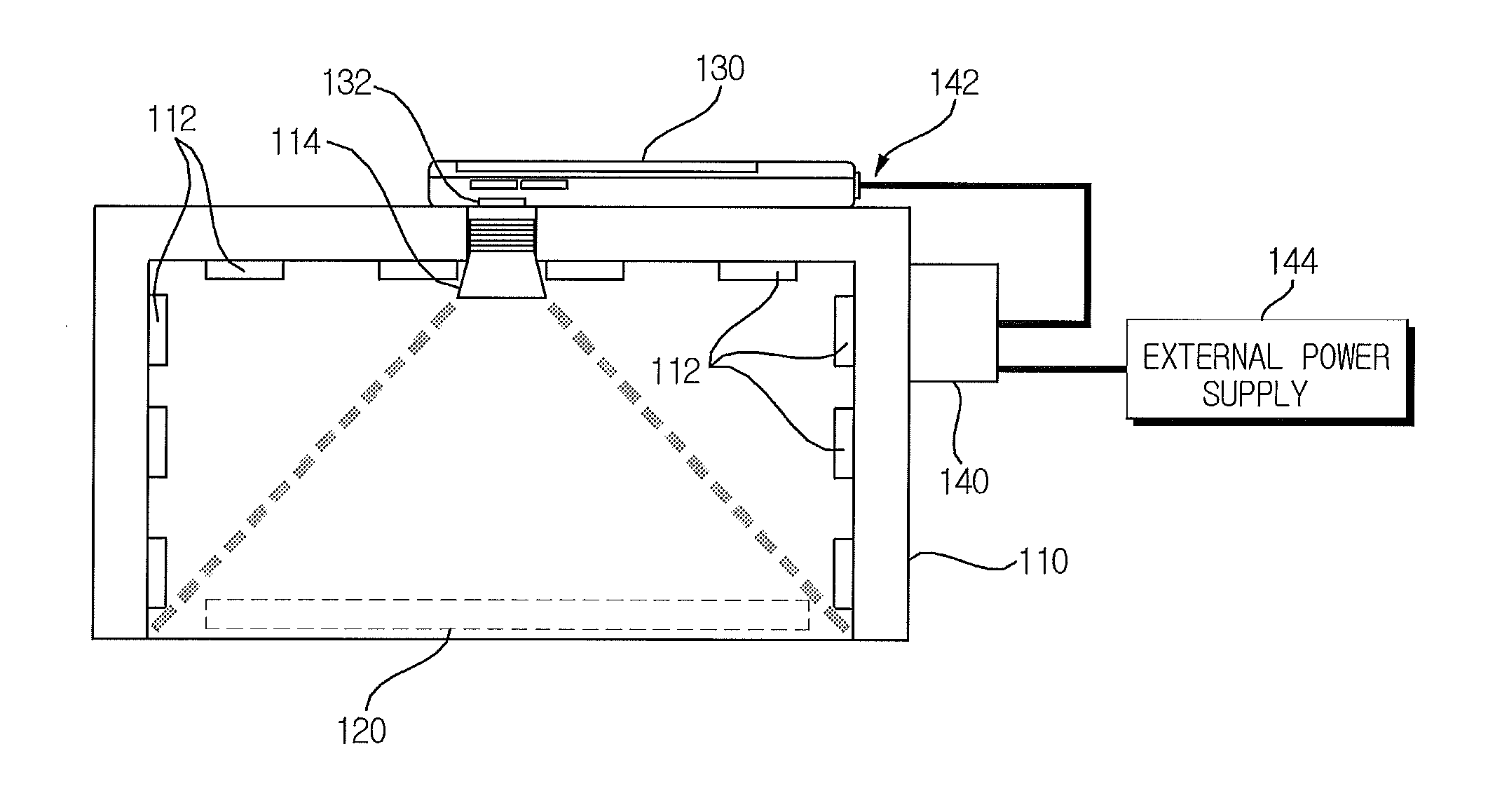
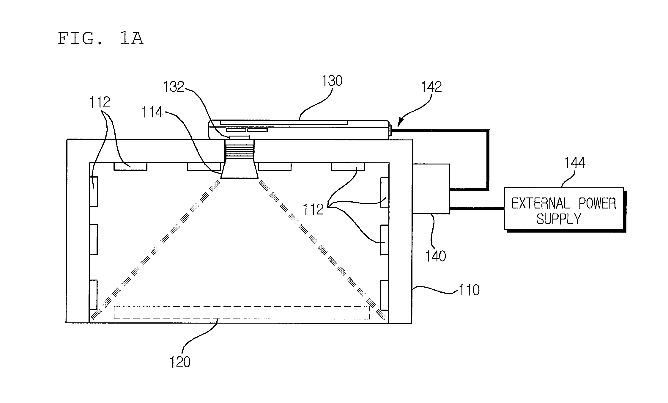
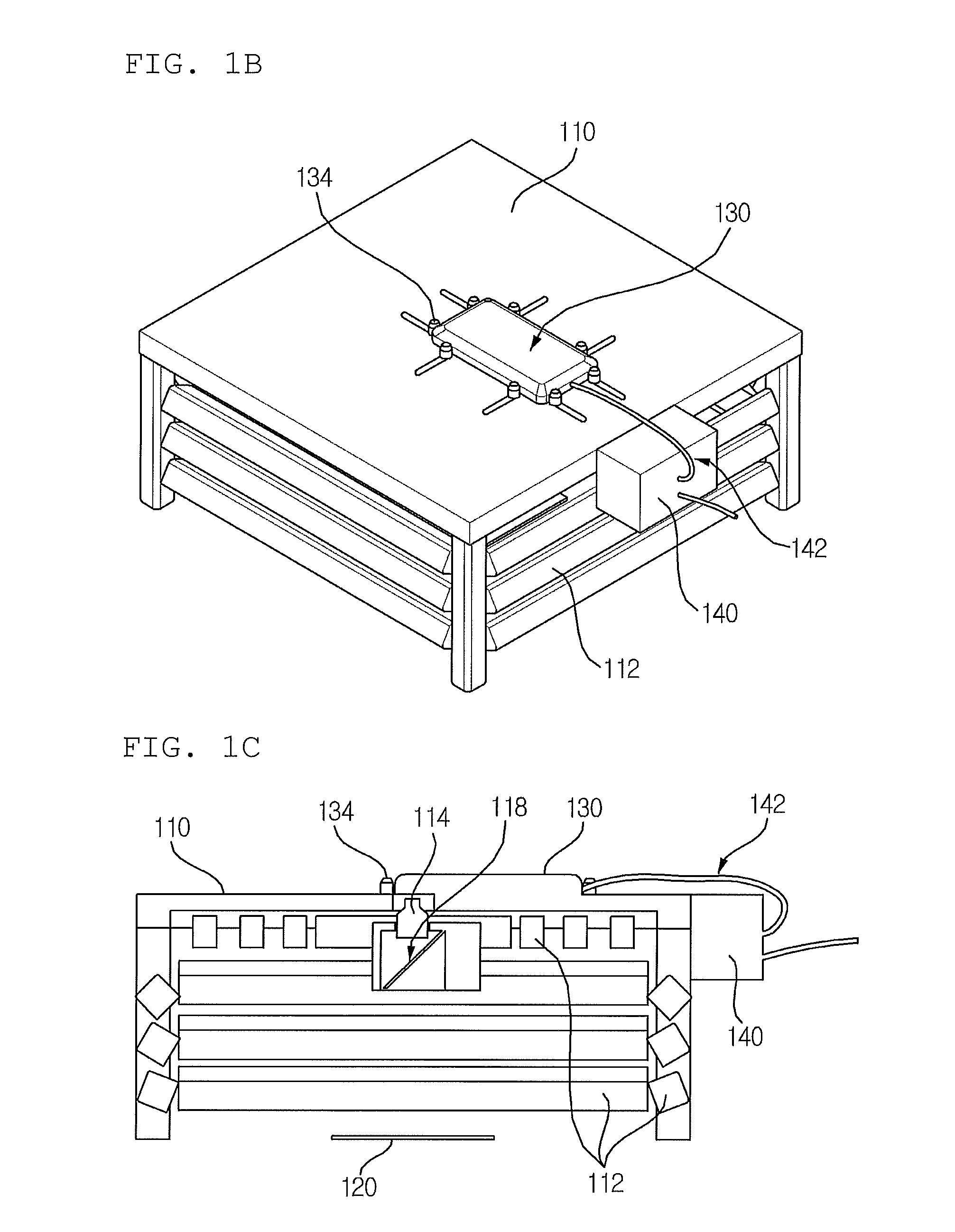
[0036]FIG. 1A is a cross-sectional view of an examining apparatus according to an exemplary embodiment of the present invention. FIG. 1B is a perspective view of the examining apparatus according to the exemplary embodiment of the present invention. FIG. 1C is a side view of the examining apparatus according to the exemplary embodiment of the present invention.

[0037]As illustrated in FIGS. 1A to 1C, an exam...


PUM


Abstract

Provided is an examining apparatus for a machine vision system according to at least an exemplary embodiment of the present invention, the examining apparatus including: a supporter including one or more illuminations that illuminate an inner part thereof and having a predetermined shape; a portable terminal having a camera function and photographing an examination object positioned in the supporter while being fixed to the supporter; and a control unit setting a photographing condition of the portable terminal according to an instruction of the portable terminal and controlling the illuminations according to the set photographing condition.

Description

CROSS-REFERENCE TO RELATED APPLICATION[0001]This application claims priority to and the benefit of Korean Patent Application No. 10-2012-0017489 filed in the Korean Intellectual Property Office on Feb. 21, 2012, the entire contents of which are incorporated herein by reference.TECHNICAL FIELD[0002]The present invention relates to a machine vision system, and more particularly, to a machine vision system primarily used for an automated lot test in a production field.BACKGROUND ART[0003]A machine vision system as a kind of factory automated system in which a camera and a computer substitute for a person who performs an operation with his / her eyes is a system in which the computer analyzes and processes video information acquired from the camera.[0004]The machine vision system is primarily used for an automated lot test in a production field, and when the machine vision system is introduced for an automation test, the machine vision system is configured by varying specifications of an ...

Claims


Application Information

Patent Timeline
IPC IPC(8): H04N5/232
CPCH04N5/23216G01N21/00H04N5/225G01N2021/8893H04N5/23225H04N5/2354G01N21/8851H04N5/232H04N23/00H04N23/60H04N23/617H04N23/74G01B11/00G01N21/88H04B1/38H04N23/62
Inventor LEE, GU YOUL
Owner M VISION
Why Eureka
Try Eureka