
Modular projector

a projector and module technology, applied in the field of projector systems, can solve the problems of subject to damage by other occupants of the room, and high cost of such devices

Inactive Publication Date: 2013-08-22
TEQUIP
View PDF7 Cites 0 Cited by
  • Summary
  • Abstract
  • Description
  • Claims
  • Application Information

AI Technical Summary

Benefits of technology

The patent text describes a modular projector mount and assembly that allows for easy attachment and relocation of a projector. The mount includes a flexible arm for easy alignment, and the assembly includes a connectivity plate that can be remote-controlled. The technical effects of this patent include improved portability, easy installation, and flexibility in image alignment and control.

Problems solved by technology

Due to the relatively high cost of such devices, financial loss due to damage and theft to these devices tends to be a problem to companies, institutions and agencies that purchase and utilize these projectors and optical presentation devices.
However, because the projector is semi-permanent and left in the room even after use, these devices are subject to theft by individuals using the room afterword, and / or may be subject to damage by other occupants of the room.
Often times, students, employees or other individuals may use a room that houses the projectors and may damage them either intentionally or inadvertently.
The cost associated with fixing and / or replacing these units may be prohibitive and may cause some institutions to only use the projectors where absolutely necessary.
Traditional presentation or audio-visual (AV) carts accommodate LCD projectors and various digital presentation devices but lack a security system to protect the devices from theft.
Although some of the security solutions may have a primary objective of theft protection, they possess certain deficiencies which fail to protect against theft but still allowing for mobility of the presentation devices.
Furthermore, many security solutions are unable to secure a variety of different types of presentation devices.
Moreover, the security systems in place to help prevent damage and theft to projectors and optical presentation devices are inefficient for other reasons.
Another problem with these type of projector units and the security devices associated with these projectors is that they lack portability of the projector and / or optical presentation device from one location to another.
This would be overly cumbersome and extremely labor intensive.
Moreover, even utilizing an AV cart may not be the best solution.
AV carts, while allowing movement of the projector from one room to another, still require significant wiring to be performed once the cart has been moved from one location to another.
Another problem associated with these AV carts is that they have to be placed in a specific location within the room to project onto the board that is usually fixed in place.
However, because the AV cart is usually rolled and moved often, and because of its location within the room, the potential for accidental bumping of the cart along with the projector associated therewith greatly increases.
On the contrary, because of its location and accessibility to more individuals within the room, the likelihood of damage to the projectors is in fact increased.
Another problem with most of the prior art projector systems is the inability to adjust the presentation angles, depth and distance from the screen on which the optical information is displayed.
And because most projectors are not able to be adjusted outside a specific vertical and horizontal maximum, the adjustment of the projectors sometimes just looks awkward, no matter how much adjustment is made to the projector and / or screen.

Method used


Image

  • Modular projector
  • Modular projector
  • Modular projector

Examples


Embodiment Construction

[0057]The following detailed description illustrates by way of example, not by way of limitation, the principles of the invention. This description will clearly enable one skilled in the art to make and use the invention, and describes several embodiments, adaptations, variations, alternatives and uses of the invention, including what is presently believed to be the best mode of carrying out the invention. It should be understood that the drawings are diagrammatic and schematic representations of exemplary embodiments of the invention, and are not limiting of the present invention nor are they necessarily drawn to scale.

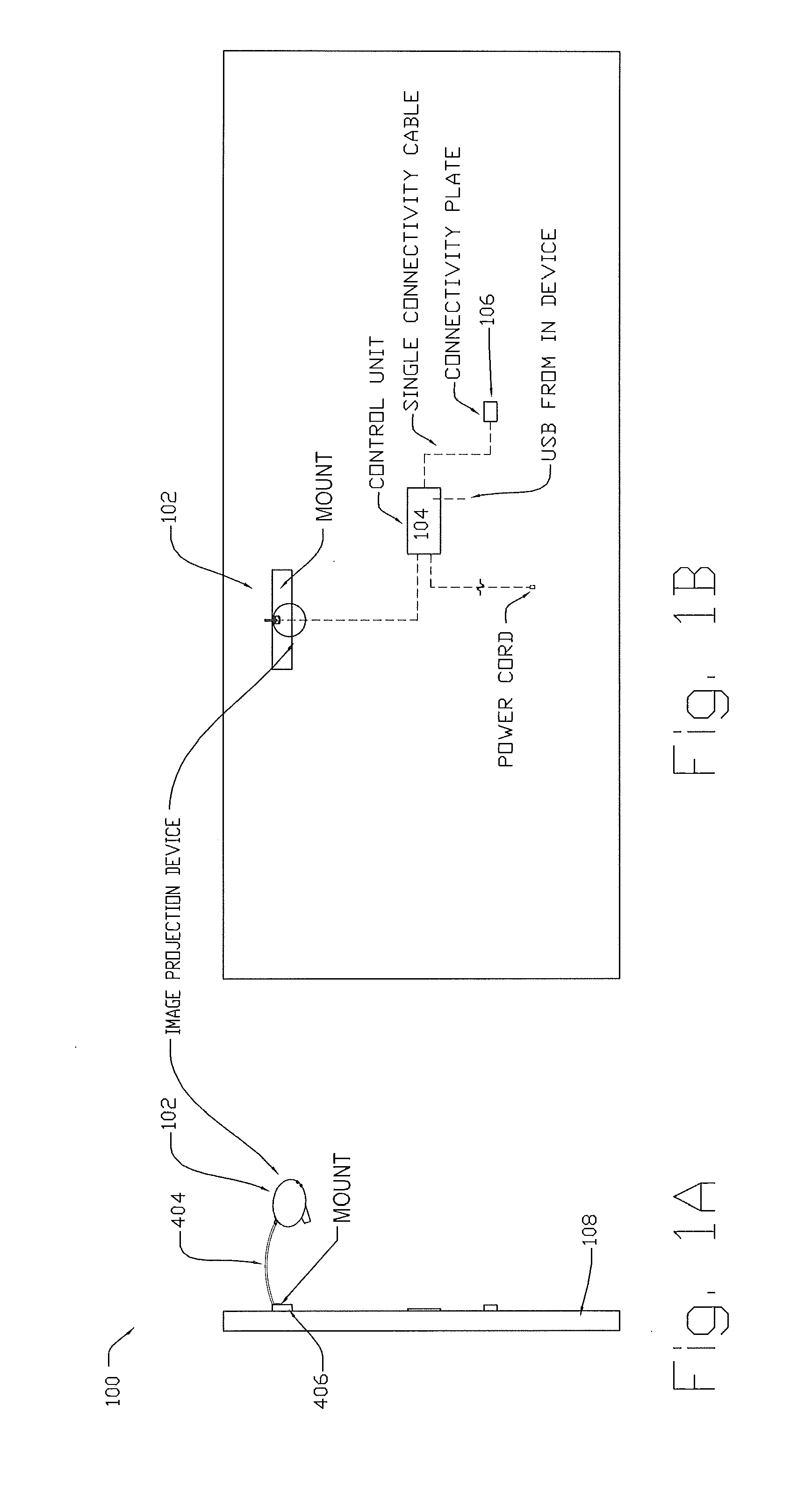
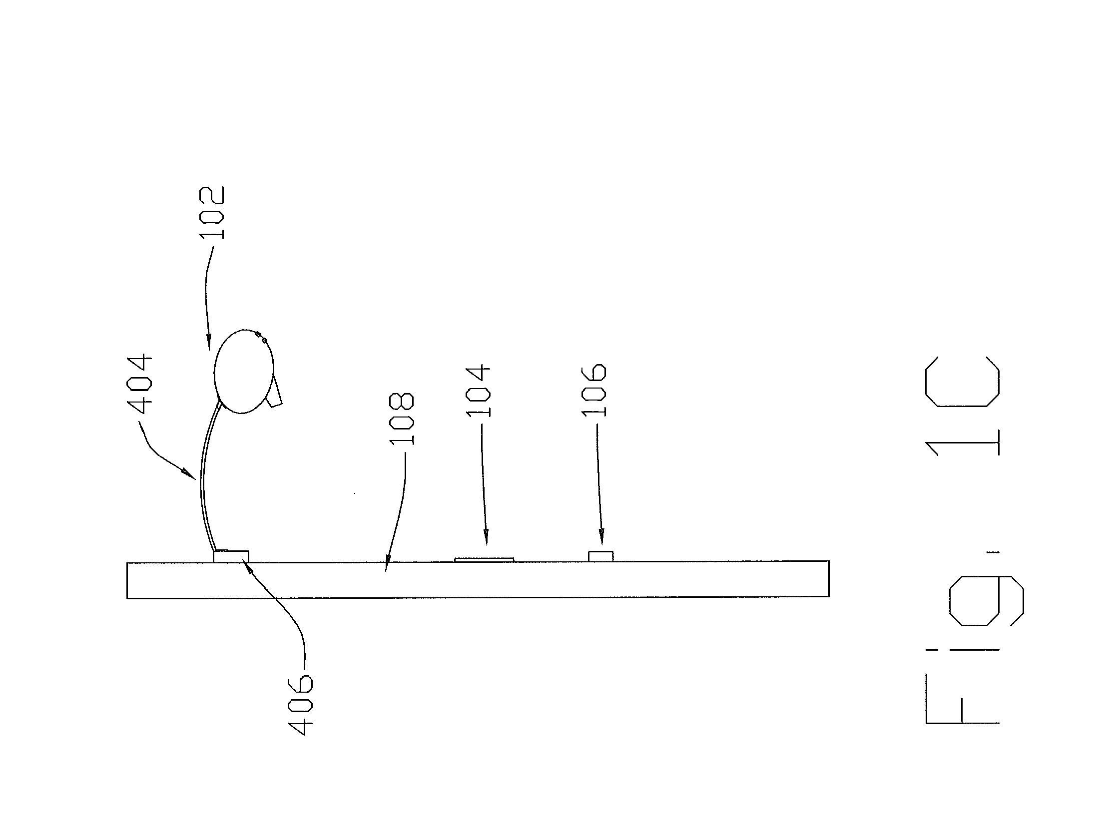
[0058]Embodiments of the present invention comprise a projection system that permits the image projection device, to be semi-permanently or permanently positioned with respect to a projector screen. The weight of the projection device is generally reduced to permit easy installation and mounting with respect to the screen. A control unit un-connectable and re-connect...


PUM

PropertyMeasurementUnit
timeaaaaaaaaaa
sizeaaaaaaaaaa
movementaaaaaaaaaa

Abstract

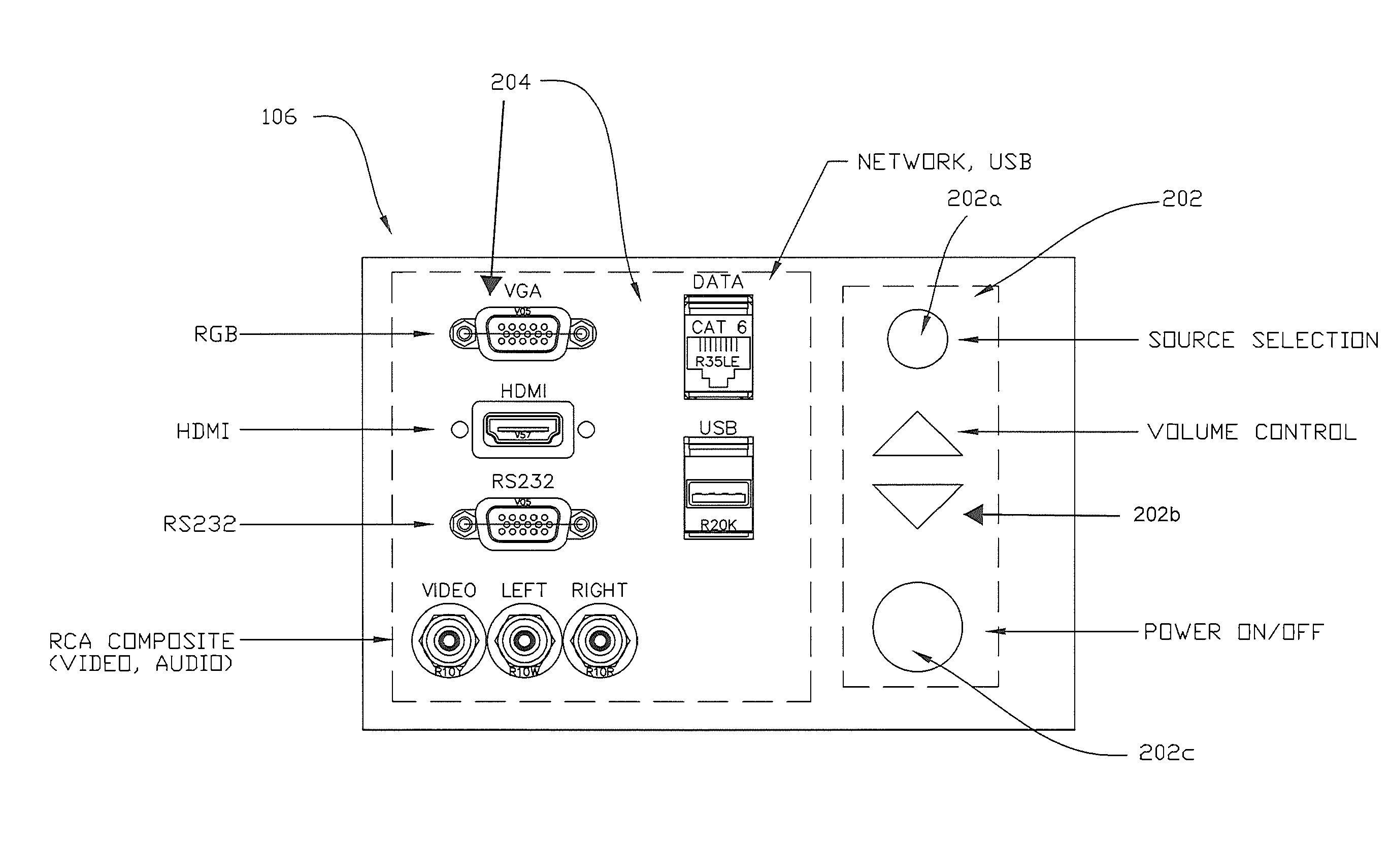
An improved modular projector assembly is provided including at least an attachment mechanism to allow the image projector to be attached to a surface closely associated with the projector screen. The modular assembly further including at least a control unit that may be connected to the image projector. The control unit may enclose the supporting hardware and software of the projector assembly and may include ports, connectors, or other interface features. The projector assembly may further include a connectivity panel associated with the control unit. The connectivity panel may provide connections and interface controls for the projection assembly.

Description

PRIORITY CLAIM[0001]This present application claims priority to the earlier filed U.S. Provisional Patent Application No. 61 / 592,330 filed on Jan. 30, 2012.FIELD OF THE INVENTION[0002]The present invention relates generally to the field of a projector system. More specifically, the present invention relates to an apparatus and system for providing a complete projector apparatus and system in communication with digital media.BACKGROUND OF THE INVENTION[0003]Projectors have been used in educational environments for some time. These projectors and optical presentation devices are used in a wide variety of industries and in various settings and applications. For example, the projectors and optical presentation devices may be utilized in classrooms for teaching applications, conference rooms for business presentations and in a plurality of other learning and training facilities to be utilized to visualize a learning concept. Due to the relatively high cost of such devices, financial loss...

Claims


Application Information

Patent Timeline
Patent Type & Authority Applications(United States)
IPC IPC(8): G03B21/14
CPCG03B21/2093Y10T29/49826G03B21/145G03B21/20
Inventor SUGARMAN, ROBSTAWICKI, ELIJAH
Owner TEQUIP
Learn More