Driving force transmission mechanism and process cartridge containing the same

a technology of driving force transmission mechanism and process cartridge, which is applied in the direction of optics, couplings of rigid shafts, electromagnetography/magnetography, etc., to achieve the effect of less manufacturing precision, easy interposition into the groove, and convenient processing

Inactive Publication Date: 2013-08-22
NINESTAR CORP
View PDF3 Cites 10 Cited by
  • Summary
  • Abstract
  • Description
  • Claims
  • Application Information

AI Technical Summary

Benefits of technology

[0034]By adoption of the technical solution, as the position-limiting mechanism and the stressed mechanism are disposed at different positions, the position-limiting mechanism cannot affect the coincidence of rotation centers during the engagement due to overlarge pressure of the stressed mechanism when being engaged with the groove, and thus the technical problem in the traditional driving force transmission mechanism that the engagement between the protrusion and the groove may be affected by the fact that the stressed mechanism may be worn due to overlarge pressure when being engaged with the groove can be solved. Moreover, as the number of the projecting teeth is two and the two projecting teeth are respectively engaged with two of the driving force transmission portion of the three vertex angles, the acting force of the image forming apparatus driving member and the photosensitive drum driving member at various positioning points can be reduced, and thus the wear of the image forming apparatus driving member and the photosensitive drum driving member can be reduced, and consequently, the technical problem that the positioning may be affected by the fact that axis centers of the image forming apparatus driving member and the photosensitive drum driving member are not coincident with each other due to wear can be solved.
[0042]7. By arrangement of the mating surfaces on the projecting teeth, the stressed area between the protrusion and the groove can be increased, and thus the wear produced between the protrusion and the groove can be reduced, and consequently, more stable driving force transmission between the photosensitive drum driving member and the image forming apparatus driving member can be realized.

Problems solved by technology

1. When the distorting protrusion is engaged with the distorting groove, the distorting angle of distorting surfaces on the protrusion and the groove is required to have high precision. When the distorting angle is inconsistent due to the manufacturing precision of the distorting surfaces on the protrusion and the groove, the distorting surfaces on the protrusion and the groove make point-to-surface contact, and one distorting surface may be deformed during the engagement between the protrusion and the groove, so that the rotation axis X1 of the drum shaft on the photosensitive drum cannot be coincident with the rotational axis X2 of the image forming apparatus driving member, and thus stable driving force transmission can be affected. In order to solve said problem, the manufacturing precision of the distorting surfaces of the protrusion and the groove is required to be high, so that the manufacturing cost can be increased and the problems such as difficult manufacture can be caused.
2. Polygonal shapes of the protrusion and the groove are difficult to process, and the manufacturing precision of the protrusion and the groove is required to be high. With an equilateral triangle as an example, the precision of the equilateral triangle protrusion and the equilateral triangle groove is required to be high, so that the precision at the triangular center can be guaranteed. Or else, the rotational axis X1 of the drum shaft on the photosensitive drum may not be coincident with the rotational axis X2 of the image forming apparatus driving member during the engagement between the protrusion and the groove, and then instable transmission can be caused. In addition, during the engagement between the protrusion and the groove, vertex angles of the triangle on the protrusion tend to be deformed after being stressed due to the requirement of driving force transmission and tend to be worn or damaged after long-term operation. Moreover, as the three vertex angles of the triangle also have the functions of stress rotation and supporting and positioning during the operation, the phenomenon that the centers X1 and X2 are not coincident with each other tends to occur during the engagement between the worn or damaged triangle and the groove, and thus stable transmission can be affected. Therefore, in order to guarantee the transmission precision and stableness, the hardness and wear resistance of materials of the triangular protrusion are required to be high. Meanwhile, as the positions at which the edges of the triangular groove make contact with the three vertex angles of the protrusion also tend to be damaged or worn during the operation, the hardness and wear resistance of the triangular groove are also required to be high.

Method used


Image

  • Driving force transmission mechanism and process cartridge containing the same
  • Driving force transmission mechanism and process cartridge containing the same
  • Driving force transmission mechanism and process cartridge containing the same

Examples


embodiment 1

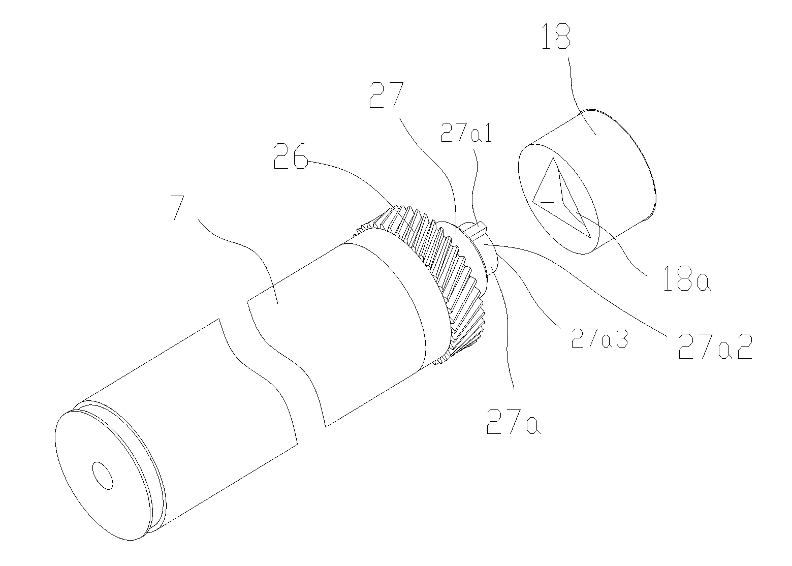
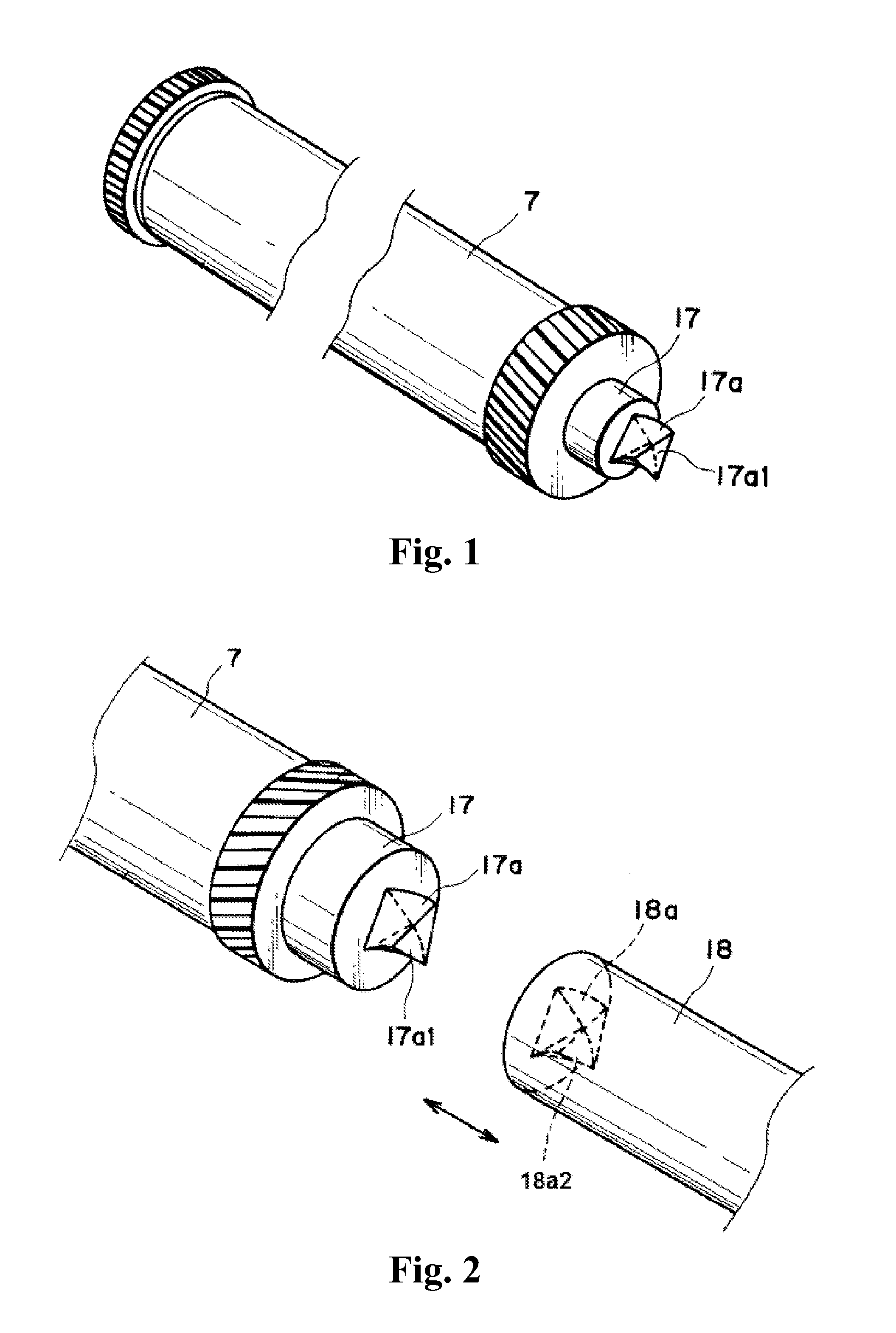
[0072]The invention relates to a driving force transmission mechanism, which comprises a photosensitive drum driving member, wherein the photosensitive drum driving member is engaged with an image forming apparatus driving member and receives the driving force from the image forming apparatus driving member; a groove is disposed on the image forming apparatus driving member; the photosensitive drum driving member comprises a protrusion which is axially extended from the end face of a photosensitive drum shaft; and the limiting between the protrusion and the groove can be realized via a mutual contact position-limiting mechanism, and the driving force transmission can be realized via a stressed mechanism.

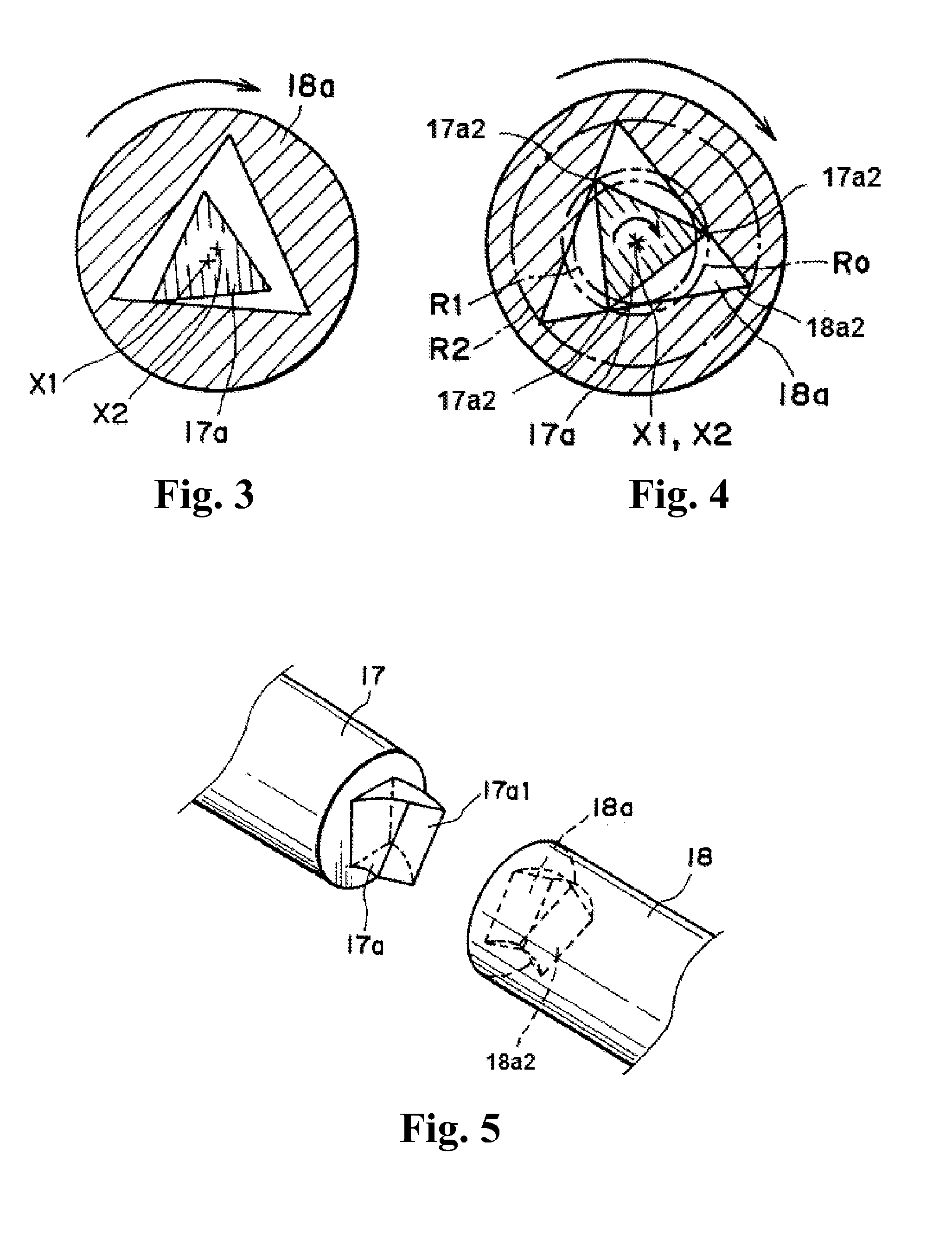
[0073]FIGS. 7 and 8 are respectively a stereogram and a top view of the image forming apparatus driving member. As illustrated in the figures, the image forming apparatus driving member 18 comprises a distorting groove 18a having a triangular cross-section and driving force transmiss...

embodiment 2

[0081]As illustrated in FIG. 11, in order to increase the contact area of a projecting tooth 27a1′ and a groove 18a and decrease the phenomenon that the projecting tooth 27a1′ is deformed due to overlarge partial pressure, the section, which makes contact with an edge of the groove 18a, on the projecting tooth 27a1′ is set to be a bevel, and the obliqueness of the bevel is basically the same with that of the edge of the groove.

embodiment 3

[0082]As illustrated in FIG. 12a, a groove 18a′ is a regular quadrangle and a supporting disc 27a2 is engaged with four edges of the groove 18a′, so that centers of a protrusion 27a and the groove 18a′ can be guaranteed to be coincident with each other. Moreover, a projecting tooth 27a1 is engaged with one edge of the groove in the groove 18a′, and the driving force is transmitted via the groove 18a′.

[0083]As illustrated in FIG. 12b, a groove 18a″ is a regular pentagon and the supporting disc 27a2 is engaged with five edges of the groove 18a″. Moreover, the projecting tooth 27a1 is engaged with one edge of the groove in the groove 18a″, and the driving force is transmitted via the groove 18a″.

[0084]It can be seen from the above that protrusions with the same structure can be applied to the grooves with different shapes.


PUM


Abstract

A driving force transmission mechanism comprising a photosensitive drum driving member, wherein the photosensitive drum driving member is engaged with an image forming apparatus driving member and receives the driving force from the image forming apparatus driving member; the image forming apparatus driving member comprises a triangular groove having a triangular cross-section and driving force transmission portion disposed in three vertex angles of the triangular groove; the photosensitive drum driving member comprises a non-distorting protrusion which is axially extended from the end face of a drum shaft and engaged with the groove on the image forming apparatus driving member; the protrusion has a position-limiting mechanism and a stressed mechanism; a projecting tooth obliquely disposed on said non-distorting protrusion is taken as the stressed mechanism; and each projecting tooth also has a mating surface which is engaged with the driving force transmission component to transmit the driving force.

Description

FIELD OF THE INVENTION[0001]The invention relates to an image forming apparatus such as a laser printer and a duplicating machine, in particular to a driving force transmission mechanism applied to the image forming apparatus and a process cartridge using the same.BACKGROUND OF THE INVENTION[0002]The traditional image forming apparatus is provided with a motor, an image forming apparatus driving member and a process cartridge, wherein the process cartridge is detachably mountable to the image forming apparatus; and a photosensitive drum is arranged on the process cartridge. During the operation of the image forming apparatus, the driving force is generated by the motor and transmitted to the process cartridge via the image forming apparatus driving member, so that the photosensitive drum on the process cartridge is driven to rotate.[0003]As illustrated in FIGS. 1 and 2, a driving force transmission mechanism is fixedly disposed at one end of the photosensitive drum 7 and comprises a...

Claims


Application Information

Patent Timeline
Patent Type & Authority Applications(United States)
IPC IPC(8): G03G15/00
CPCF16D1/108F16D1/10G03G21/186F16D2001/102
Inventor PENG, QINGFEILIANG, JUN
Owner NINESTAR CORP
Why Eureka
Try Eureka