Waste Disposal Device

a technology of a disposal device and a waste disposal chamber, which is applied in the direction of specific use bioreactors/fermenters, grain treatment, biomass after-treatment, etc., can solve the problems of unsatisfactory stirring and shredding effect, unpleasant odor generation, and leakage, and achieves efficient stirring, shredding, heat and dry kitchen waste, and prevents odor leakage

Inactive Publication Date: 2013-08-22
KITCHEN UTENSIL
View PDF6 Cites 29 Cited by
  • Summary
  • Abstract
  • Description
  • Claims
  • Application Information

AI Technical Summary

Benefits of technology

[0005]An object of the present invention is to provide a waste disposal device which can efficiently stir, shred, heat and dry kitchen waste and which prevents odor leakage.

Problems solved by technology

In such conventional waste disposal device, unpleasant odor is generated and leaks out during storage of the loaded kitchen waste or the heating process.
Besides, as the rotary shaft extends in a horizontal direction, the stirring and shredding effect is unsatisfactory.

Method used


Image

  • Waste Disposal Device
  • Waste Disposal Device
  • Waste Disposal Device

Examples


Embodiment Construction

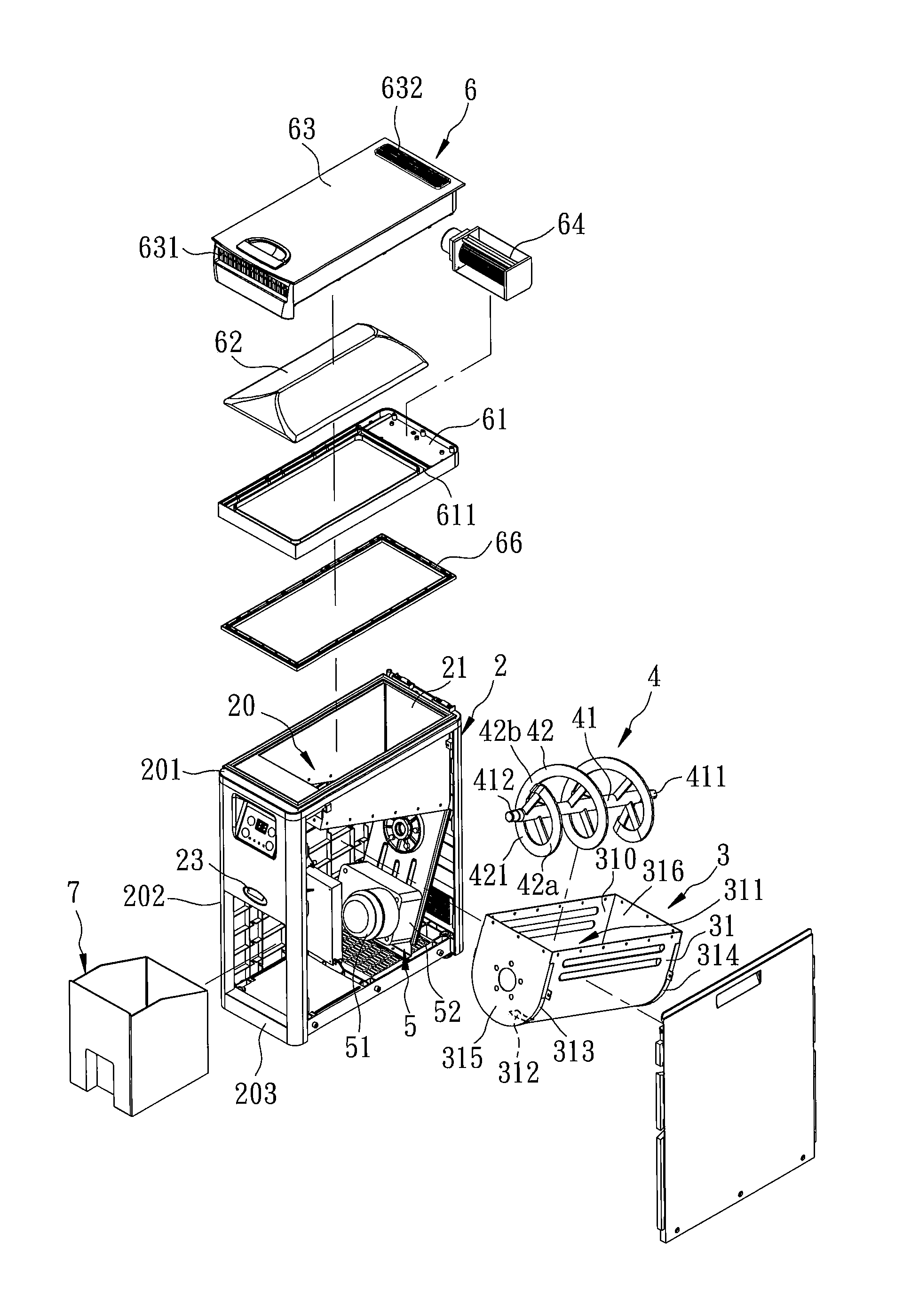
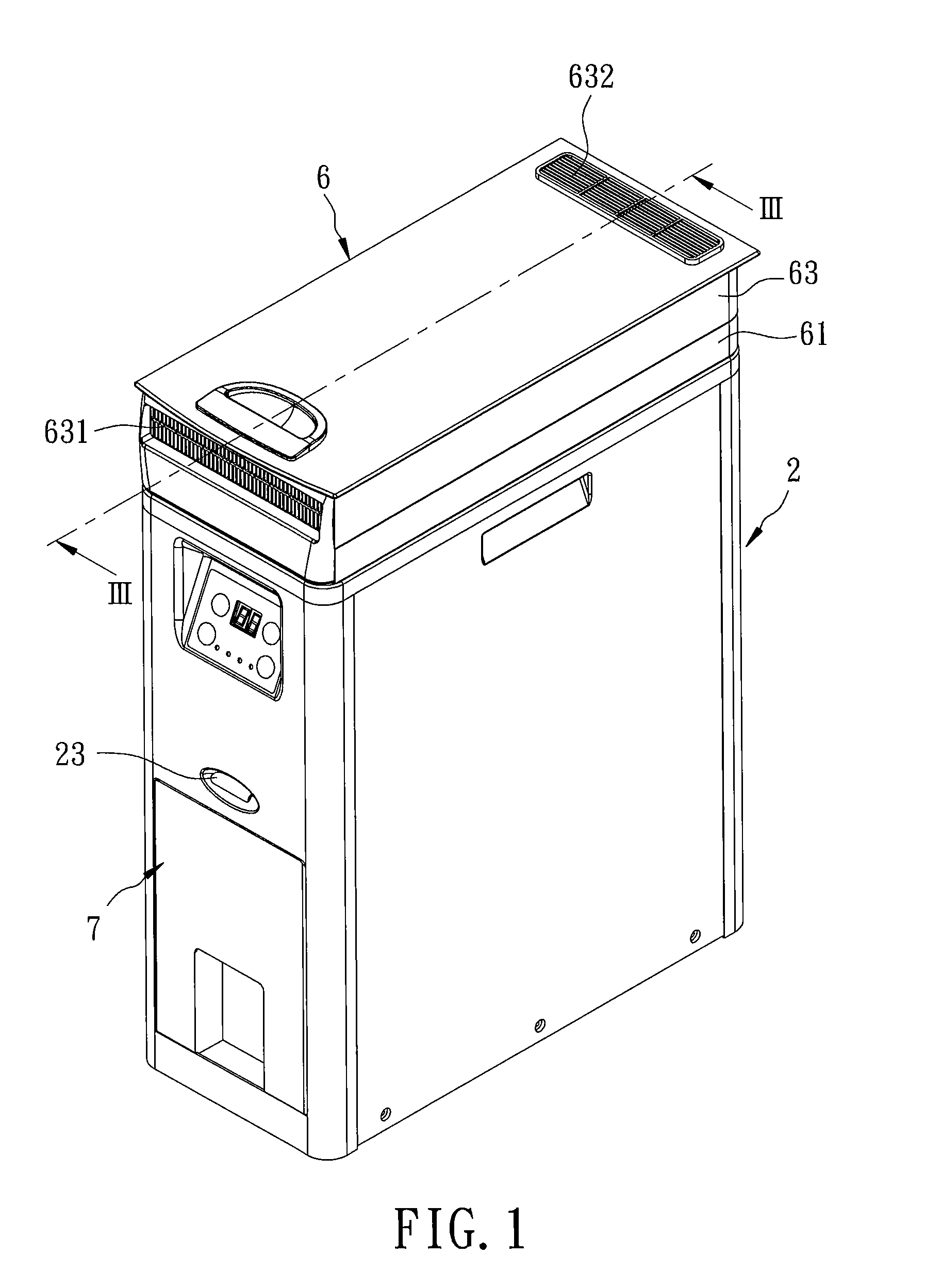
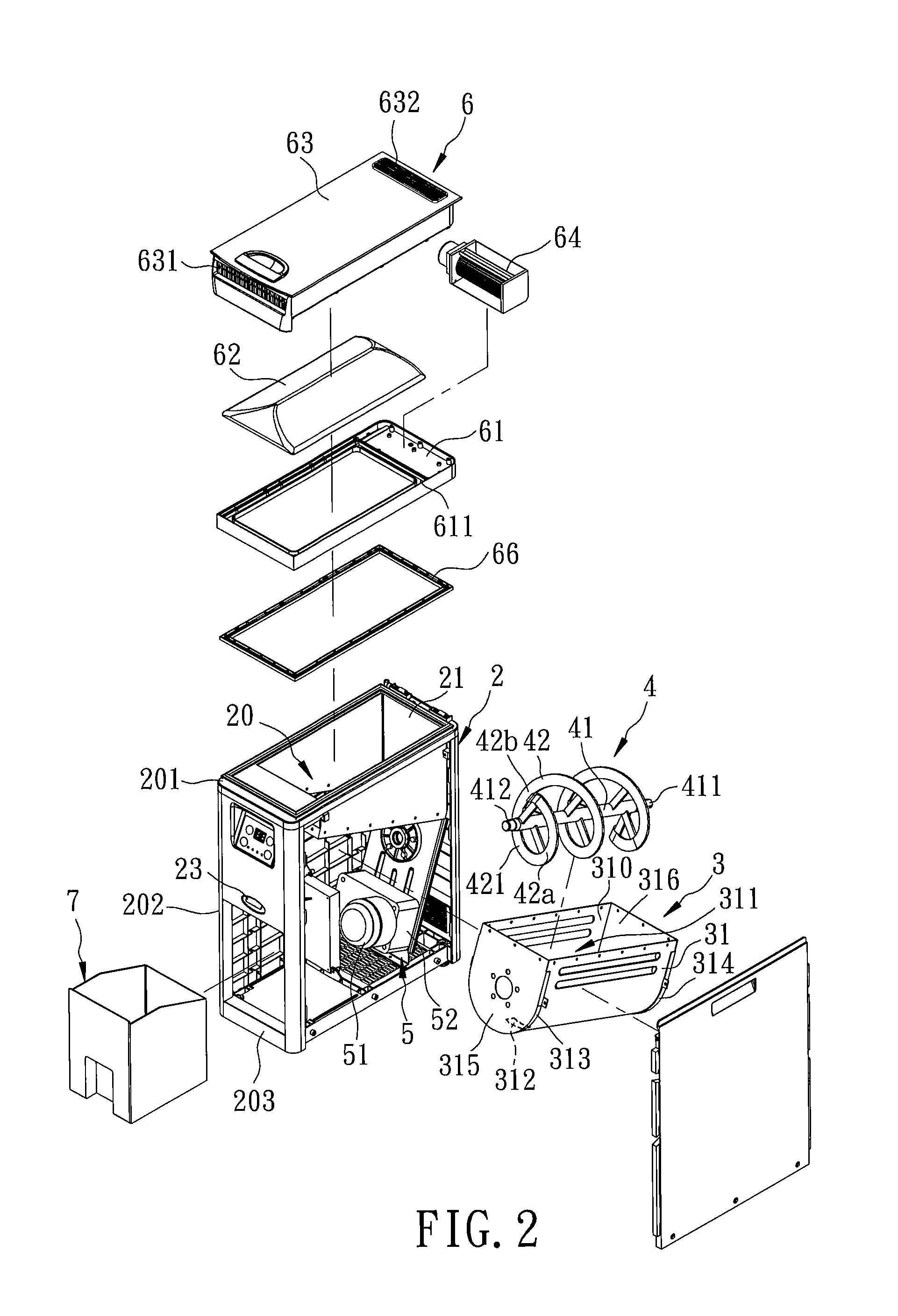
[0016]Referring to FIGS. 1 to 3, an embodiment of a waste disposal device according to the present invention is shown to comprise a housing 2, a tank unit 3, a grinder assembly 4, a drive unit 5, a condensing unit 6, and collection bin 7.

[0017]The housing 2 has top and bottom ends 201, 203 spaced apart from each other in an upright direction, and a surrounding wall 202 extending between the top and bottom ends 201, 203 so as to cooperatively define a housing chamber 20. The top end 201 has an access opening 21 for loading of kitchen waste thereinto. The surrounding wall 202 has a drain port 22 disposed adjacent to the bottom end 203. The housing 2 further has an operating handle 23 which is movably mounted on a front side thereof.

[0018]The tank unit 3 includes a grinder tank 31 which is disposed in the housing chamber 20 and which extends along an axis (L) that is oriented to be inclined relative to the bottom end 203, and a heating element 32 which is disposed on an outer rounded s...


PUM

PropertyMeasurementUnit
angleaaaaaaaaaa
angleaaaaaaaaaa
angleaaaaaaaaaa

Abstract

A waste disposal device includes a grinder tank disposed within a housing and having an inner rounded surface angularly extending about an axis for loading of kitchen waste therein, and a grinder assembly rotatably mounted in the tank about the axis to stir and shred the waste and configured to force the waste to advance forward so that the shredding and drying process can be carried out efficiently. A condensing unit is disposed to cool and condense hot air in the housing into water which is drained through a drain port to thereby reduce leakage of unpleasant odor through an access opening of the housing.

Description

BACKGROUND OF THE INVENTION[0001]1. Field of the Invention[0002]This invention relates to a waste disposal device, more particularly to a waste disposal device for stirring, shredding and drying kitchen waste.[0003]2. Description of the Related Art[0004]A conventional waste disposal device, such as that disclosed in U.S. Pat. Nos. 5,710,042 and 6,620,613, generally includes a grinder tank for loading of kitchen waste thereinto, a rotary shaft having vanes or blades rotatably mounted into the grinder tank to stir and shred the loaded kitchen waste, and a heater disposed to heat and dry the loaded kitchen waste during the stirring and shredding process. In such conventional waste disposal device, unpleasant odor is generated and leaks out during storage of the loaded kitchen waste or the heating process. Besides, as the rotary shaft extends in a horizontal direction, the stirring and shredding effect is unsatisfactory.SUMMARY OF THE INVENTION[0005]An object of the present invention is...

Claims


Application Information

Patent Timeline
Patent Type & Authority Applications(United States)
IPC IPC(8): C12M1/10
CPCC12M27/06C12M45/02C12M45/20C05F9/02B02C18/04B02C23/18B02C18/0084Y02A40/20
Inventor CHANG, KUANG-NAN
Owner KITCHEN UTENSIL
Why Eureka
Try Eureka