Method of manufacturing rigid-flexible printed circuit board

a printed circuit board and rigid-flexible technology, applied in the direction of laminating printed circuit boards, paper/cardboard containers, removing conductive materials by irradiation, etc., can solve the problems of difficult application of conventional wire bonding or tape automated bonding (tab) technique, and damage to the base substra

Active Publication Date: 2013-08-29
SAMSUNG ELECTRO MECHANICS CO LTD
View PDF4 Cites 26 Cited by
  • Summary
  • Abstract
  • Description
  • Claims
  • Application Information

AI Technical Summary

Problems solved by technology

In order to connect the pads provided with a fine pitch to the pad provided on the wiring substrate, since very high accuracy is required for wiring on the wiring substrate or positioning upon connection, it is very difficult to apply a conventional wire bonding or tape automated bonding (TAB) technique.
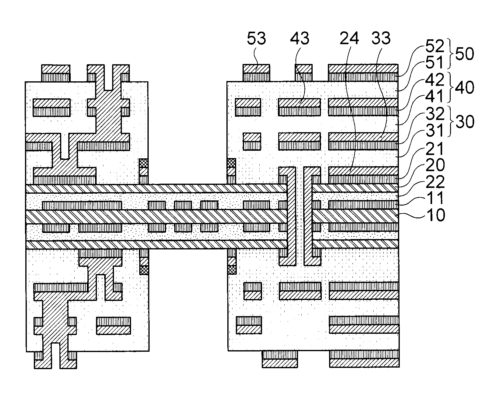
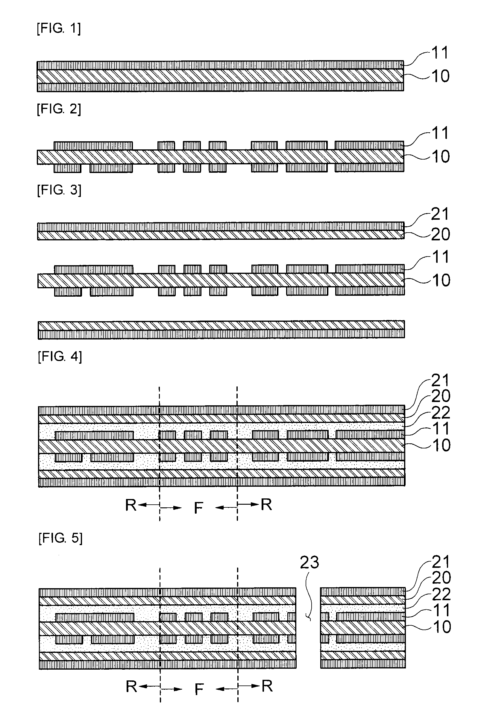
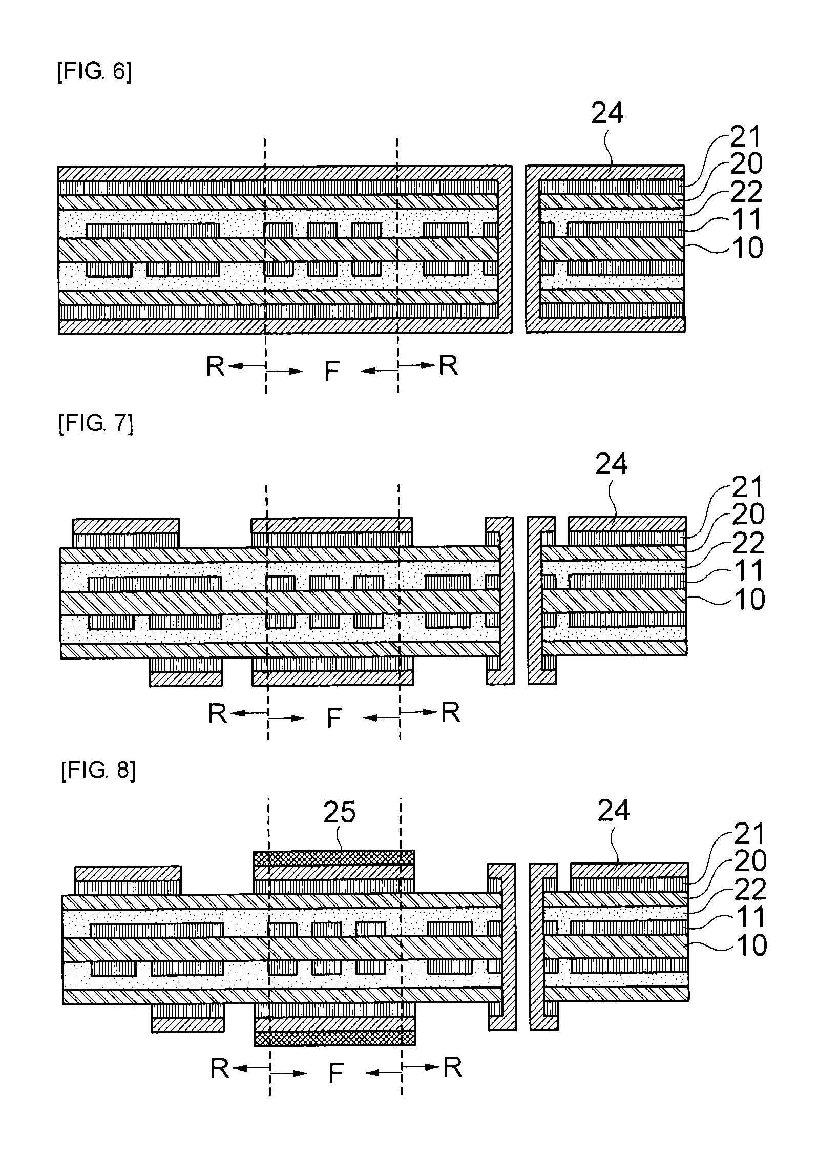
However, when looking into the claim of the related art document, like a conventional typical process of manufacturing a printed circuit board, a rigid-flexible printed circuit board is finally completed through the steps of providing a base substrate divided into a rigid domain R and a flexible domain F, laminating a plurality of circuit layers on the base substrate, and removing the circuit layer in the flexible domain F. In this case, the base substrate may be also damaged by laser light when removing the circuit layer in the flexible domain F. Generally, when laminating a plurality of circuit layers, oxidation (for example, brown or black oxidation) is performed on a surface of the circuit layer, that is, a surface of a metal layer on which a circuit pattern is formed, for improvement of adhesion between the circuit layers.
Finally, the laser light is irradiated to the base substrate (flexible film) in the process of removing the circuit layer in the flexible domain F, thus causing damage to the base substrate.
Like this, according to the conventional method of manufacturing a rigid-flexible printed circuit board, the base substrate in the flexible domain F may be damaged, thus eventually causing product defects.

Method used


Image

  • Method of manufacturing rigid-flexible printed circuit board
  • Method of manufacturing rigid-flexible printed circuit board
  • Method of manufacturing rigid-flexible printed circuit board

Examples


Embodiment Construction

[0044]Advantages and features of the present invention and methods of accomplishing the same will be apparent by referring to embodiments described below in detail in connection with the accompanying drawings. However, the present invention is not limited to the embodiments disclosed below and may be implemented in various different forms. The exemplary embodiments are provided only for completing the disclosure of the present invention and for fully representing the scope of the present invention to those skilled in the art. Like reference numerals refer to like elements throughout the specification.

[0045]Terms used herein are provided to explain embodiments, not limiting the present invention. Throughout this specification, the singular form includes the plural form unless the context clearly indicates otherwise. When terms “comprises” and / or “comprising” used herein do not preclude existence and addition of another component, step, operation and / or device, in addition to the abov...


PUM

PropertyMeasurementUnit
sizeaaaaaaaaaa
sizeaaaaaaaaaa
sizeaaaaaaaaaa

Abstract

The present invention relates to a method of manufacturing a rigid-flexible printed circuit board including: providing a first flexible film having a first metal layer on one or both surfaces; forming a circuit pattern by patterning the first metal layer; forming a second flexible film, which has a second metal layer on one surface, on one or both surfaces of the first flexible film; forming a circuit pattern by patterning the second metal layer in a rigid domain R; providing an anti-oxidation protective layer on the second metal layer in a flexible domain F; laminating at least one circuit layer on the second flexible film; and removing the circuit layer in the flexible domain F.

Description

CROSS-REFERENCE TO RELATED APPLICATIONS[0001]Claim and incorporate by reference domestic priority application and foreign priority application as follows:[0002]“CROSS REFERENCE TO RELATED APPLICATION[0003]This application claims the benefit under 35 U.S.C. Section 119 of Korean Patent Application Serial No. 10-2012-0019149, entitled filed Feb. 24, 2012, which is hereby incorporated by reference in its entirety into this application.”BACKGROUND OF THE INVENTION[0004]1. Field of the Invention[0005]The present invention relates to a method of manufacturing a rigid-flexible printed circuit board, and more particularly, to a method of manufacturing a rigid-flexible printed circuit board including a process of providing an anti-oxidation protective layer.[0006]2. Description of the Related Art[0007]In recent times, as the degree of integration of semiconductor elements is gradually increasing, the number of pads provided on the semiconductor elements to connect the semiconductor elements ...

Claims


Application Information

Patent Timeline
Patent Type & Authority Applications(United States)
IPC IPC(8): H05K3/00
CPCH05K3/4644H05K3/4691H05K3/0058Y10T156/1082Y10T156/10Y10T156/1064H05K3/02H05K3/361H05K3/4611H05K2203/06H05K1/02H05K3/46H05K1/0278H05K1/0298H05K1/118H05K3/0026H05K3/027H05K3/285H05K2201/0154
Inventor LEE, YANG JESHIN, JAE HOYANG, DEK GIN
Owner SAMSUNG ELECTRO MECHANICS CO LTD
Why Eureka
Try Eureka