Tube for heat exchanger

a technology of heat exchanger and tube, which is applied in the direction of manufacturing tools, soldering devices, light and heating equipment, etc., can solve the problem that the fluid flowing in the flat tube is likely to leak to the outside, and achieve the effect of improving the brazing performance of the bonded portion of the tube for a heat exchanger

Inactive Publication Date: 2013-08-29
DENSO CORP
View PDF0 Cites 6 Cited by
  • Summary
  • Abstract
  • Description
  • Claims
  • Application Information

AI Technical Summary

Benefits of technology

[0016]In this way, even in a case where the extended portion in the inner wall portion is constructed as the inner fin, even if the compressive force is applied to the tube in the minor radius direction when the tube for a heat exchanger is assembled, the position of the tip end portion opposite to the flat plate portion in the inner wall portion is only shifted and adhesion between the inner wall and the outer wall portion and adhesion between the extended portion in the inner wall portion and the inner peripheral face of the other curved portion can be held. As a result, the brazing performance in the bonded portion in the tube for a heat exchanger can be improved.

Problems solved by technology

In this case, if a brazing material is not suitably introduced into the bonded portion in the flat tube, a fluid flowing in the flat tube is likely to leak to the outside because of faulty brazing.

Method used


Image

  • Tube for heat exchanger
  • Tube for heat exchanger
  • Tube for heat exchanger

Examples


first embodiment

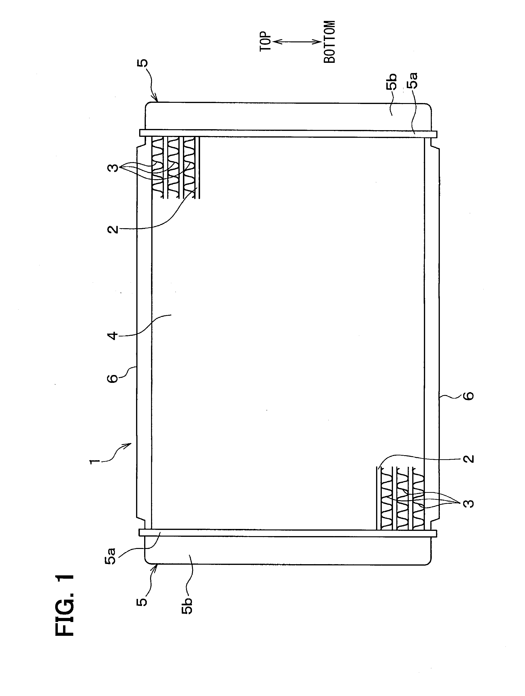
[0030]A first embodiment of the present invention will be described on the basis of FIG. 1 to FIG. 7. FIG. 1 is a front view of a radiator 1 according to the present embodiment.

[0031]In the present embodiment, a flat tube (tube for a heat exchanger) 2 is applied to a radiator 1 for exchanging heat between an engine cooling water (heat exchange medium) for cooling a vehicle engine (internal combustion engine) and air (atmosphere).

[0032]The flat tube 2 in FIG. 1 is a tube in which the engine cooling water flows. The flat tube 2 is formed in a flat shape in such a way that a direction in which air flows (direction vertical to a plane of paper of FIG. 1) is aligned with a major radius direction. Further, a plural number of flat tubes 2 are arranged parallel to each other in a vertical direction in FIG. 1 in such a way that its longitudinal direction is aligned with a horizontal direction in FIG. 1. A detailed description of the flat tube 2 will be provided later.

[0033]An outer fin (corr...

second embodiment

[0057]Next, a second embodiment of the present invention will be described on the basis of FIG. 8(a) and FIG. 8(b). Here, FIG. 8(a) and FIG. 8(b) are section views to show a flow passage section of a flat tube 2 of the present embodiment. FIG. 8(a) shows an entire flow passage section of the flat tube 2 and FIG. 8(b) shows a partial enlarged view of a portion B in FIG. 8(a). In the present embodiment, the descriptions of parts similar to or equivalent to those in the first embodiment will be omitted or simplified.

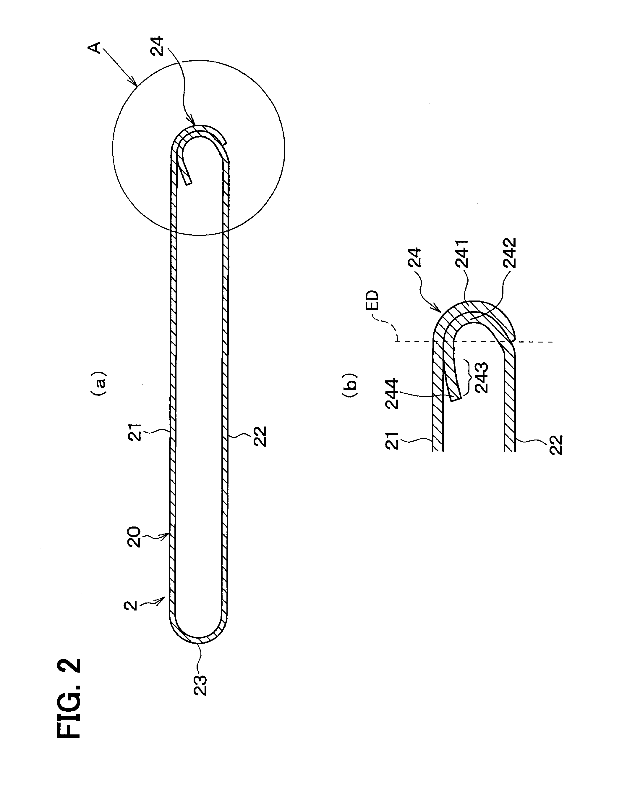
[0058]The flat tube 2 of the present embodiment has an extended portion 243 in which an inner wall portion 242 is extended from a portion opposite to an outer wall portion 241 to a first curved portion 23. In the extended portion 243, a portion (fin portion 243a) opposite to the respective flat plate portions 21, 22 in a minor radius direction of the flat tube 2 is formed in a wavy shape in such a way as to function as an inner fin for increasing a heat transfer area for an...


PUM

PropertyMeasurementUnit
radiusaaaaaaaaaa
shapeaaaaaaaaaa
lengthaaaaaaaaaa

Abstract

A cylindrical member of a tube for a heat exchanger is made of a pair of flat plate portions, and a pair of curved portions for connecting the pair of flat plate portions to each other. One of the pair of curved portions constructs a bonded portion in which an outer wall portion and an inner wall portion are bonded to each by brazing in a state where the outer wall portion and the inner wall portion overlap each other. The inner wall portion has a portion opposite to the outer wall portion put into close contact with the outer wall portion and is bonded to the one flat plate portion in a state where a tip end portion of the inner wall portion opposite to the one flat plate portion is separated from the one flat plate portion.

Description

CROSS REFERENCE TO RELATED APPLICATION[0001]This application is based on Japanese Patent Application No. 2010-252807 filed on Nov. 11, 2010, the contents of which are incorporated herein by reference in its entirety.TECHNICAL FIELD[0002]The present invention relates to a tube for a heat exchanger, which can be usefully applied to, for example, a radiator of an automobile or the like.BACKGROUND ART[0003]A flat tube formed by bending a plate-shaped part (for example, a metal plate) has been known as a tube for a heat exchanger. These flat tubes and corrugated fins are alternately stacked on each other to thereby form a heat exchange core, and a tank and piping for introducing a heat exchange medium are coupled to the heat exchange core, so that a heat exchanger is constructed.[0004]This kind of flat tube is made of: a pair of flat plate portions which are opposite to each other with a given gap between them in a minor radius direction; a curved portion which is curved and connected to...

Claims


Application Information

Patent Timeline
Patent Type & Authority Applications(United States)
IPC IPC(8): F28F3/08
CPCB21C37/14B21C37/151F28D1/0391F28F3/086F28D1/05366F28D2021/0094F28F2275/04B23K1/0012
Inventor OOHARA, TAKAHIDEHAMADA, HIROSHIYOSHIDO, NORIOSAKAKIBARA, TETSUYAMITSUKAWA, KAZUHIROOU, UGENDA, HIROYUKISAITOU, MITSUYOSHINAKABOU, TADASHIMIYAZAKI, NORIYUKIBABA, NORIMASASHIMANUKI, HIROYASU
Owner DENSO CORP
Why Eureka
Try Eureka