Aluminum alloy brazing filler metal and brazing plate

A technology of aluminum alloy and brazing filler metal, which is applied in the direction of welding medium, welding equipment, metal processing equipment, etc., can solve the problems that cannot be dealt with, and the technology has not been fully researched, and achieves less brazing filler metal thickness, excellent fluidity, excellent The effect of brazeability

Inactive Publication Date: 2014-10-01
KOBE STEEL LTD
View PDF10 Cites 2 Cited by
  • Summary
  • Abstract
  • Description
  • Claims
  • Application Information

AI Technical Summary

Problems solved by technology

However, the existing technology has not sufficiently studied the improvement of the fluidity of the solder itself, and cannot deal with it.

Method used


Image

  • Aluminum alloy brazing filler metal and brazing plate
  • Aluminum alloy brazing filler metal and brazing plate
  • Aluminum alloy brazing filler metal and brazing plate

Examples


Embodiment

[0066] Next, the present invention will be described in more detail based on examples.

[0067]

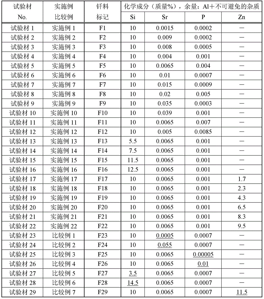
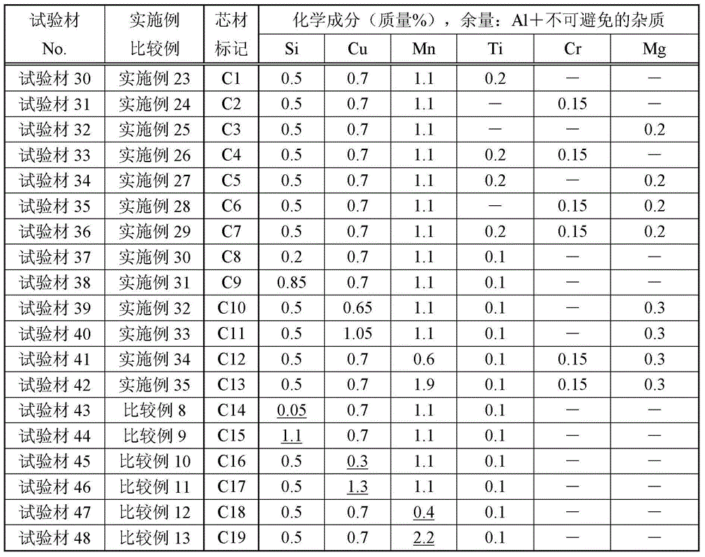
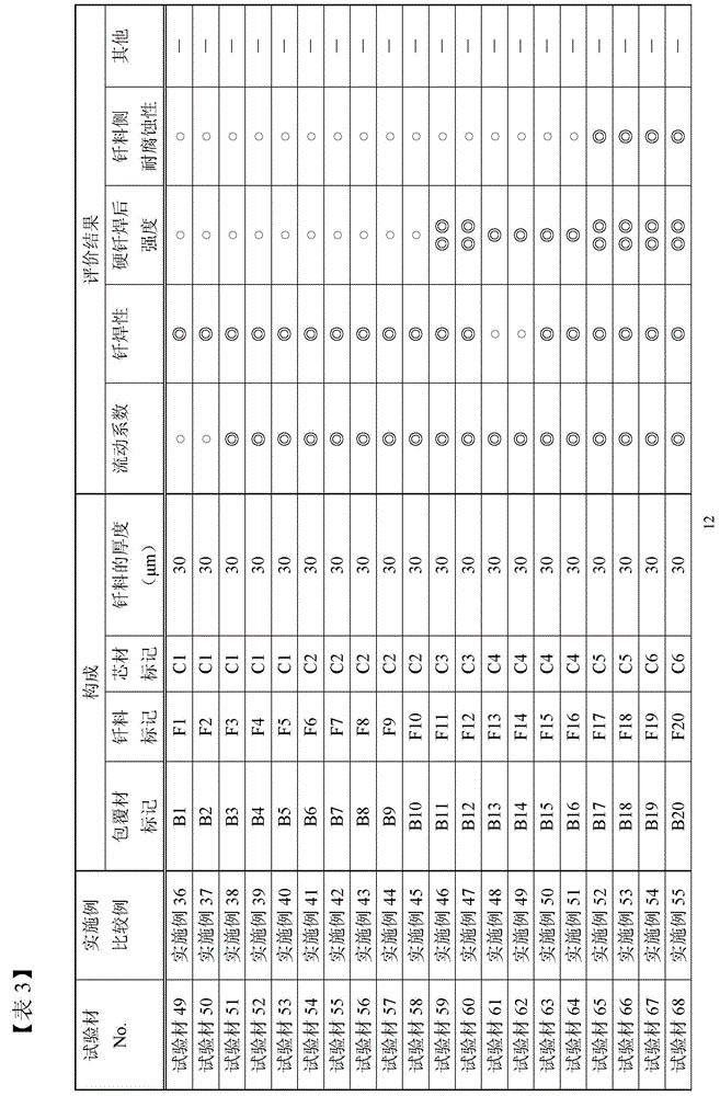
[0068] Brazing filler metals (test material Nos. 1 to 29, brazing filler metal symbols F1 to F29) having the chemical components shown in Table 1 were produced by a general method. Cast ingots of core materials (test materials No. 30 to 48, core material codes C1 to C19) having the chemical composition shown in Table 2, perform homogenization treatment, and cut the end face to a predetermined plate thickness to produce cores material. For the core material and brazing material produced by these, various combinations are made to overlap them, and the brazing material / core material two-layer cladding material is crimped and rolled by hot rolling, then cold rolling, intermediate annealing, and final rolling are performed. Brazing sheet test materials (test materials No. 49 to 95, and clad material codes B1 to B47)) which are clad materials with a plate thickness of 0.25 mmt were p...


PUM


Abstract

The invention discloses an aluminum alloy brazing filler metal constituted by Si in a range from 4.0 to 13.0wt%, Sr 0.001 to 0.050wt%, P 0.0001 to 0.0090 wt%, and other aluminum alloy formed by A1 and other inevitable foreign matters and a brazing plate using the same. The aluminum alloy brazing filler metal has advantages of excellent, strength, hard-solder performance, and anti-corrosion performance.

Description

technical field [0001] The present invention relates to an aluminum alloy brazing filler metal for brazing and an aluminum alloy brazing sheet using the brazing filler metal. Background technique [0002] Conventionally, as a raw material for heat exchangers such as automobiles, a brazing alloy consisting of an aluminum alloy (hereinafter, sometimes simply referred to as "Al alloy") with a brazing filler metal on one or both sides of the core material has been used. plate (hereinbelow, there are cases where it is only referred to as "brazing plate"). For example, it is used as a core material in the tubes of heat exchangers such as intercoolers, radiators, oil coolers, condensers, radiator cores, evaporators, header plates, and side brackets used in automobiles. At least one side of the brazing plate is coated with a brazing material composed of an Al-Si alloy. These brazing plates are each molded into a predetermined shape, and then the respective members are joined in a ...

Claims


Application Information

Patent Timeline
IPC IPC(8): B23K35/28B23K3/08
CPCB23K35/0238B23K35/288
Inventor 植田利树木村申平泉孝裕涩谷雄二德田健二
Owner KOBE STEEL LTD
Why Eureka
Try Eureka