Eureka AIR delivers breakthrough ideas for toughest innovation challenges, trusted by R&D personnel around the world.

High target utilization moving magnet planar magnetron scanning method

a scanning method and moving magnet technology, applied in the field of magnetic sputtering, can solve the problems of increasing the effective target erosion area, increasing the overall target utilization, and difficult to achieve ideals, etc., to achieve enhanced target utilization, enhanced target utilization, and better target utilization

Inactive Publication Date: 2013-08-29
GENERAL PLASMA
View PDF3 Cites 0 Cited by
  • Summary
  • Abstract
  • Description
  • Claims
  • Application Information

AI Technical Summary

Benefits of technology

The patent describes a method for operating a moving magnet magnetron that improves target utilization. The method involves moving the magnet pack in a first 2-D motion profile with a variable velocity and then translating it in a second 2-D motion profile that varies relative to the first profile. This process results in a pattern of erosion that does not have a typical diamond shape, instead having multiple erosion peaks. This pattern of erosion is more efficient than the traditional diamond shape, improving target utilization.

Problems solved by technology

This movement results in an increase of the effective target erosion area and hence increases the overall target utilization.
However, this ideal is especially difficult to achieve at the magnetron turn-around region 3, because as the magnet pack is moved under the target, the arc geometry of the turn-around crosses over itself at the center region.
While several prior art attempts have been made to mitigate this effect, these attempts have met with limited success based on the weight percent of target utilization being at most about 48%.
As can be seen, all these scanning profiles result in extra target erosion at the diamond area.

Method used


Image

  • High target utilization moving magnet planar magnetron scanning method
  • High target utilization moving magnet planar magnetron scanning method
  • High target utilization moving magnet planar magnetron scanning method

Examples


Embodiment Construction

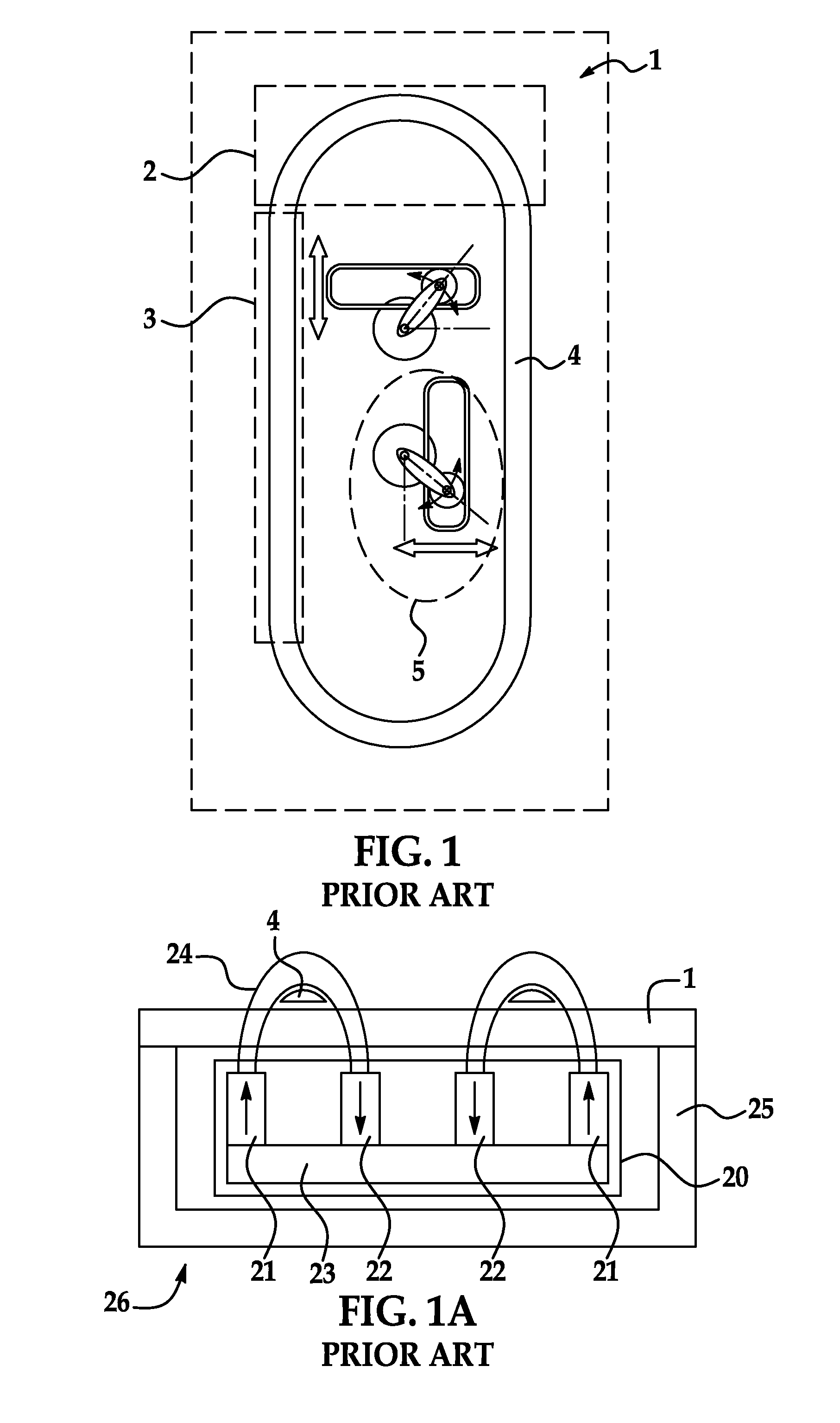
[0025]The present invention has utility in increasing target utilization of a moving magnet planar magnetron (MMPM). The present invention provides a novel method of magnet pack scanning that combines multiple magnet motion profiles to produce non-overlapping motion paths over the deepest erosion groove locations of a target.

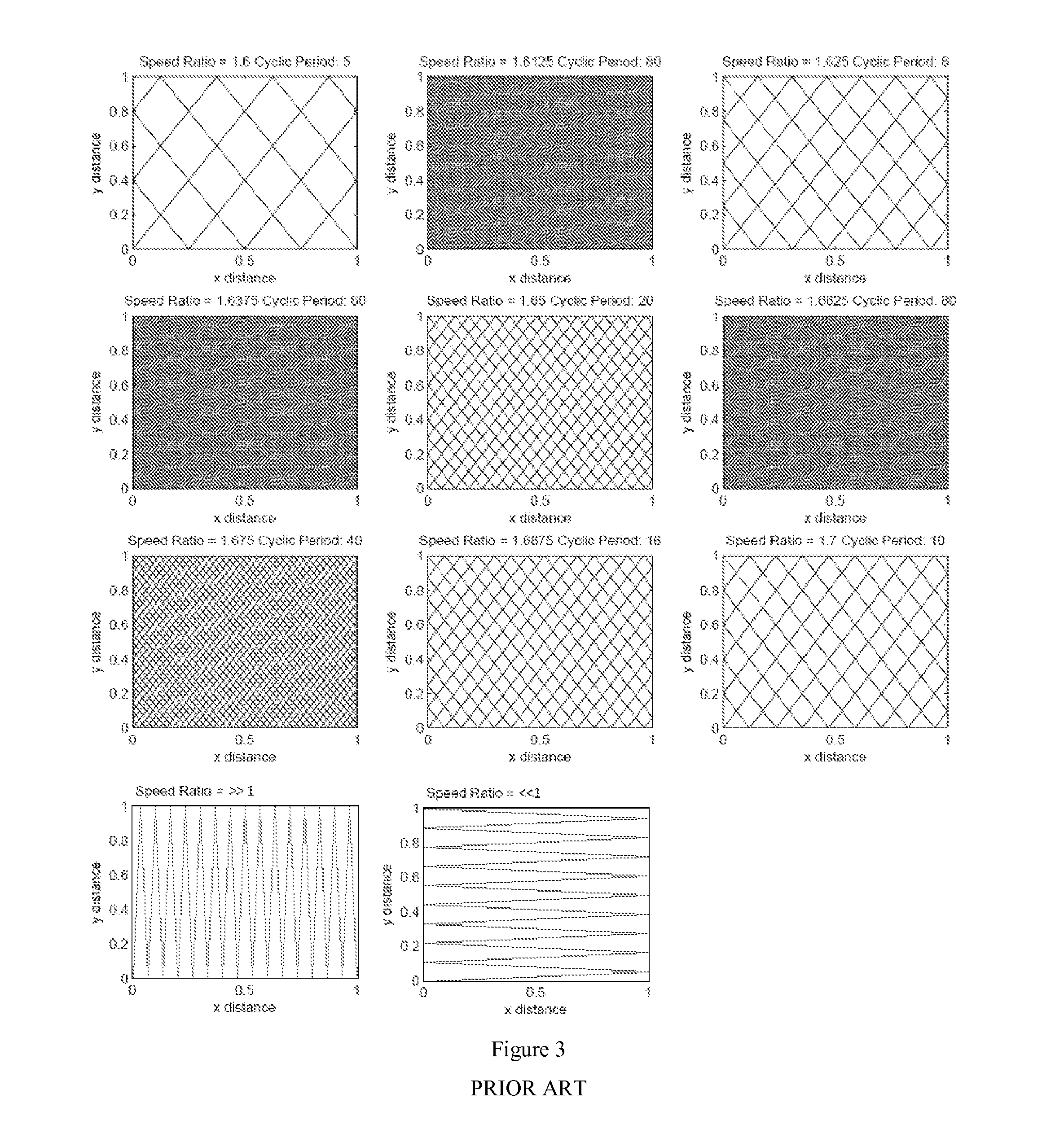
[0026]To improve target utilization and avoid a premature wear groove or spot, an inventive magnet pack motion profile spreads the target erosion area over a larger area relative to conventional MMPMs while target wear remote from deepest erosion groove locations is comparatively unchanged. The present invention introduces a novel magnet pack scanning method that overcomes premature wear in the diamond area. The inventive scanning method involves moving the magnet pack at constant linear speed on 2-D perpendicular axes and varying the speed ratio between the two axes to afford non-overlapping motion paths.

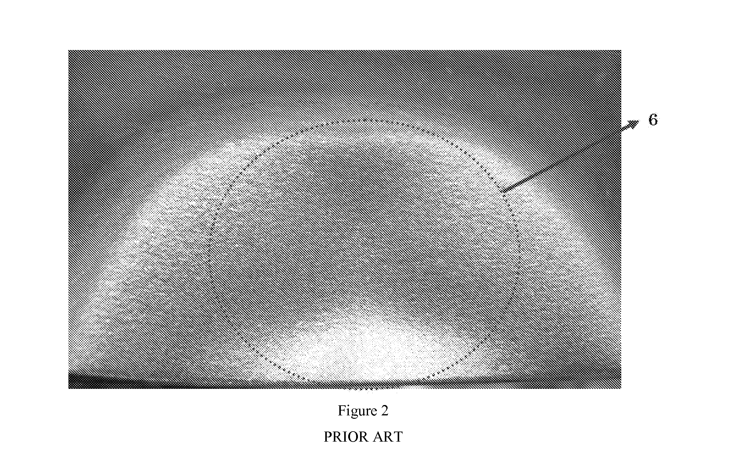
[0027]The present invention generates localized target er...


PUM

PropertyMeasurementUnit
weight percentaaaaaaaaaa
velocityaaaaaaaaaa
zero accelerationaaaaaaaaaa

Abstract

A method for operating a moving magnet magnetron is provided enhanced target utilization. A magnet pack is moved in a first 2-D motion profile with a variable velocity. The magnet pack is then translated in a second 2-D motion profile that varies relative to the first profile. This process moving and translating is repeated to provide enhanced target utilization. These varied movement and translation profiles preclude the formation of a diamond-shaped erosion area common to the prior art. Representative to such profiles are intersecting sigmoidal curves. The resultant target is characterized by a metal from that has better target utilization as the wear pattern precludes the diamond shaped erosion area common to the prior art and instead has a multiple erosion peaks.

Description

RELATED APPLICATIONS[0001]This application claims priority benefit of U.S. Provisional Application No. 61 / 346,158 filed May 19, 2010; the contents of which are hereby incorporated by reference.BACKGROUND[0002]1. Field of the Invention[0003]The present invention relates generally to magnetron sputtering and, in particular, to scanning methods for moving magnet planar magnetrons to improve the target utilization.[0004]2. Background of the Invention[0005]Moving magnet planar magnetron (MMPM) sputtering is well known in the art. FIG. 1 and FIG. 1A show a prior art 2-axis moving magnet planar magnetron 26 with sputter racetrack 4 on the outer surface of the planar target 1. The magnet pack 20 has the ability to move within the planar magnetron housing 25 during sputtering operation that moves the sputter racetrack erosion area 4 on planar target 1. This movement results in an increase of the effective target erosion area and hence increases the overall target utilization.[0006]MMPMs move...

Claims


Application Information

Patent Timeline
Patent Type & Authority Applications(United States)
IPC IPC(8): C23C14/35C23C14/34
CPCC23C14/3414C23C14/35C23C14/3407H01J37/3455H01J37/3405
Inventor NGO, PHONG
Owner GENERAL PLASMA
Why Eureka
Eureka Blog
Learn More