Eureka AIR delivers breakthrough ideas for toughest innovation challenges, trusted by R&D personnel around the world.

Protective cover structure for physical vapor deposition apparatus and physical vapor deposition apparatus

A technology of physical vapor deposition and shielding, which is applied in ion implantation plating, metal material coating process, coating, etc., can solve the problem of waste of target material, reduce cost, improve target material utilization rate, and increase deposition rate Effect

Inactive Publication Date: 2019-07-12
HUAIAN IMAGING DEVICE MFGR CORP
View PDF4 Cites 0 Cited by
  • Summary
  • Abstract
  • Description
  • Claims
  • Application Information

AI Technical Summary

Problems solved by technology

[0004] However, the sputtered metal ions and atoms may be attached to the shield of the reaction chamber during the deposition process, resulting in waste of target materials

Method used


Image

  • Protective cover structure for physical vapor deposition apparatus and physical vapor deposition apparatus
  • Protective cover structure for physical vapor deposition apparatus and physical vapor deposition apparatus
  • Protective cover structure for physical vapor deposition apparatus and physical vapor deposition apparatus

Examples


Embodiment Construction

[0022] The following description provides specific application scenarios and requirements of the application, with the purpose of enabling those skilled in the art to manufacture and use the contents of the application. Various local modifications to the disclosed embodiments will be readily apparent to those skilled in the art, and the general principles defined herein may be applied to other embodiments and embodiments without departing from the spirit and scope of the disclosure. application. Thus, the present disclosure is not limited to the embodiments shown, but is to be accorded the widest scope consistent with the claims.

[0023] The technical solution of the present invention will be described in detail below in conjunction with the embodiments and the accompanying drawings.

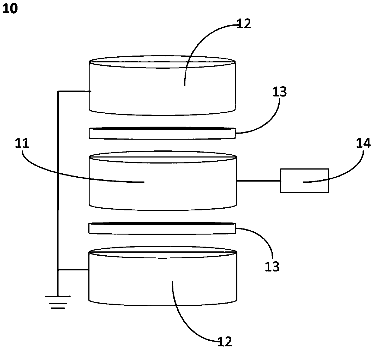
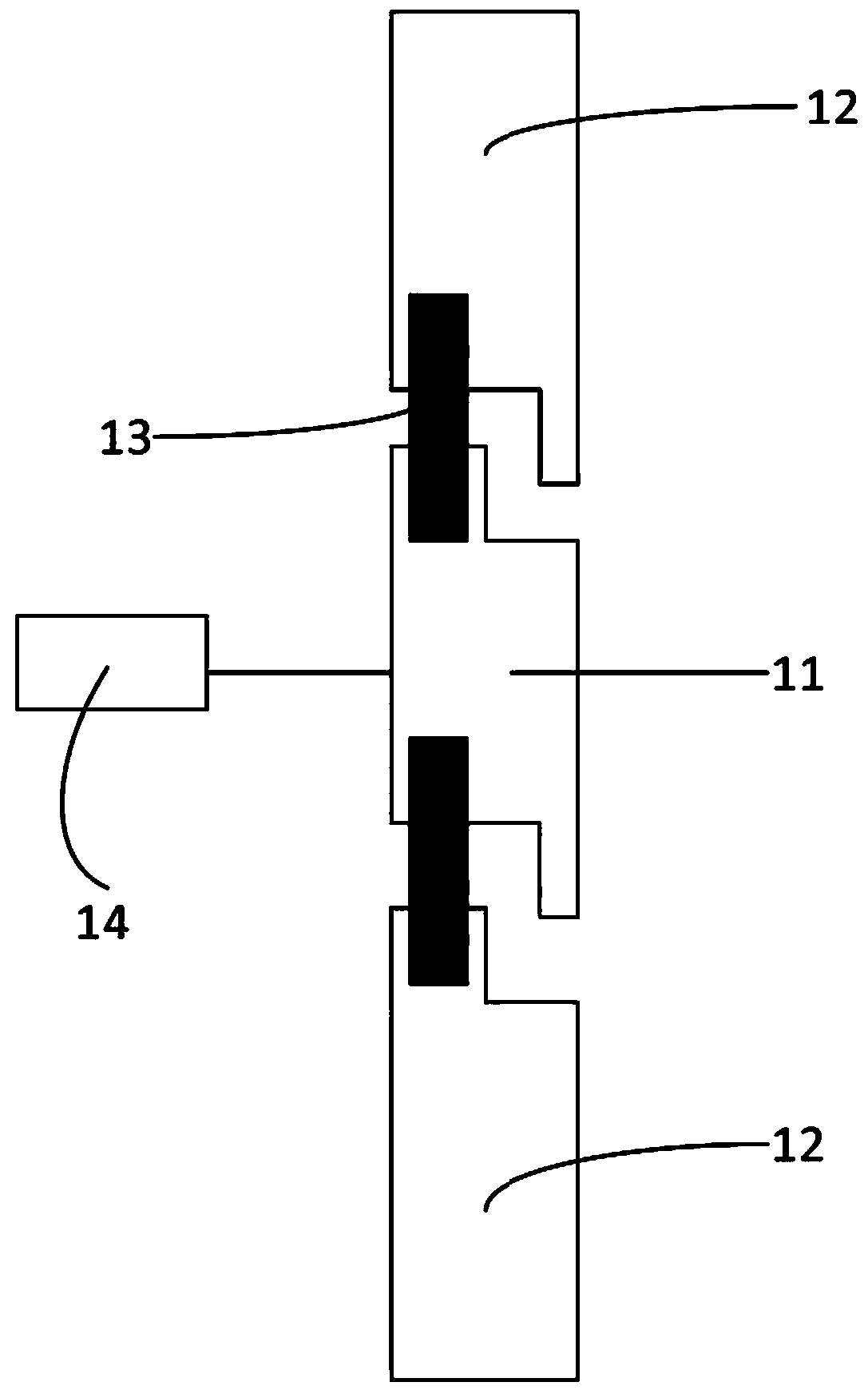
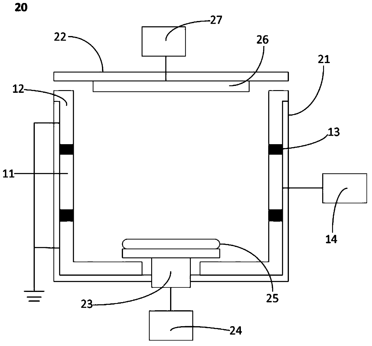
[0024] figure 1 A shield structure 10 for physical vapor deposition equipment is schematically shown, including: a first shield 11; at least one second shield 12; at least one insulating memb...


PUM


Abstract

The invention provides a protective cover structure for a PVD apparatus and the PVD apparatus comprising the protective cover. The protective cover structure includes a first protective cover, at least one second protective cover, at least one insulating component, a third power supply device, wherein the insulating component is arranged between the first protective cover and the second protectivecover, and the first protective cover is electrically insulated and connected with the second protective cover; and the third power supply device is electrically connected with the first protective cover. The protective cover structure for the PVD apparatus and the PVD apparatus comprising the protective cover, the deposition rate of the PVD process is improved, the utilization rate of the targetmaterial is improved, and therefore the process cost is reduced.

Description

technical field [0001] The present disclosure relates to the field of semiconductor manufacturing, and in particular, relates to a shield structure for physical vapor deposition equipment and a physical vapor deposition equipment including the shield structure. Background technique [0002] In semiconductor wafer manufacturing, physical vapor deposition methods include evaporation and sputtering. Among them, the vapor deposition method heats the vapor deposition source, and utilizes the saturated vapor pressure of the vapor deposition source at high temperature to deposit the thin film. The sputtering method uses low-voltage, high-current arc discharge technology to ionize the inert gas in the reaction chamber under vacuum conditions, and then under the action of electric field and negative voltage, the gas ions bombard the metal target and sputter out. The process of depositing metal ions and atoms on the wafer surface. [0003] Generally, physical vapor deposition equipm...

Claims


Application Information

Patent Timeline
IPC IPC(8): C23C14/34
CPCC23C14/34
Inventor 王大为吴孝哲吴龙江林宗贤
Owner HUAIAN IMAGING DEVICE MFGR CORP
Why Eureka
Eureka Blog
Learn More