Eureka AIR delivers breakthrough ideas for toughest innovation challenges, trusted by R&D personnel around the world.

Sputtering system and method for highly magnetic materials

a high-magnet material, sputtering technology, applied in the direction of electrolysis components, vacuum evaporation coatings, coatings, etc., to achieve the effect of reducing vibration and load on the system, high speed and high ra

Inactive Publication Date: 2016-05-12
INTEVAC
View PDF6 Cites 0 Cited by
  • Summary
  • Abstract
  • Description
  • Claims
  • Application Information

AI Technical Summary

Benefits of technology

[0008]Disclosed herein is a sputtering system and method that enhance uniformity of the film formed on the substrate, and also enables high throughput. One embodiment provides a system wherein substrates continually move in front of the sputtering target. The magnetron is linearly scanned back and forth at speed that is at least several times higher than the speed on the substrates' motion. The magnetron is scanned in the direction of substrate travel and then in the reverse direction, repeatedly. During most of its travel, the magnetron is moved at a constant speed. However, as it approaches the end of its travel, is decelerates. Then, when is starts its travel in the opposite direction, it accelerates until it reaches the constant speed. The deceleration / acceleration in one embodiment is 0.5 g and in another it is 1 g. This enhances utilization of the target. According to another embodiment, the turning point of the magnetron is changed at successive scans, so as to define a zone of turnaround. This also helps in enhancing target utilization.
[0016]According to further aspects of the invention, a sputtering arrangement for a deposition chamber is provided, comprising a target having a front surface and a back surface, and having sputtering material provided on its front surface; A movable magnet mechanism having a magnet configured for reciprocally scanning in close proximity to the back surface of the target and a counterweight configured for reciprocally scanning at same speed but opposite direction as the magnet. By having the counterweight move at the same speed but opposite direction of the mag, vibrations and loads on the system are reduced, and the magnet can be scanned at much higher speeds and be accelerated and decelerated at much higher rates. The movable magnet mechanism includes a motive element which is energized to reciprocally move the target and the counterweight, wherein the magnet and the counterweight are mechanically coupled to the motive element. The motive element may be a deformable tension element, examples of which include a belt, a timing belt, a chain, etc. A motor is coupled to the motive element to energize the motive element, and a controller provides signals to activate the motor.

Problems solved by technology

However, as it approaches the end of its travel, is decelerates.

Method used


Image

  • Sputtering system and method for highly magnetic materials
  • Sputtering system and method for highly magnetic materials
  • Sputtering system and method for highly magnetic materials

Examples


Embodiment Construction

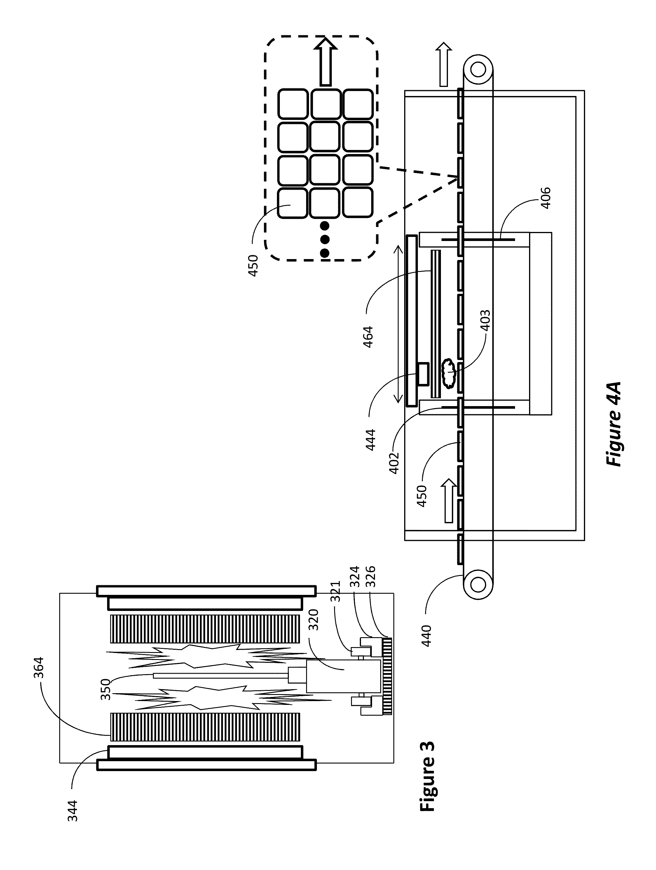
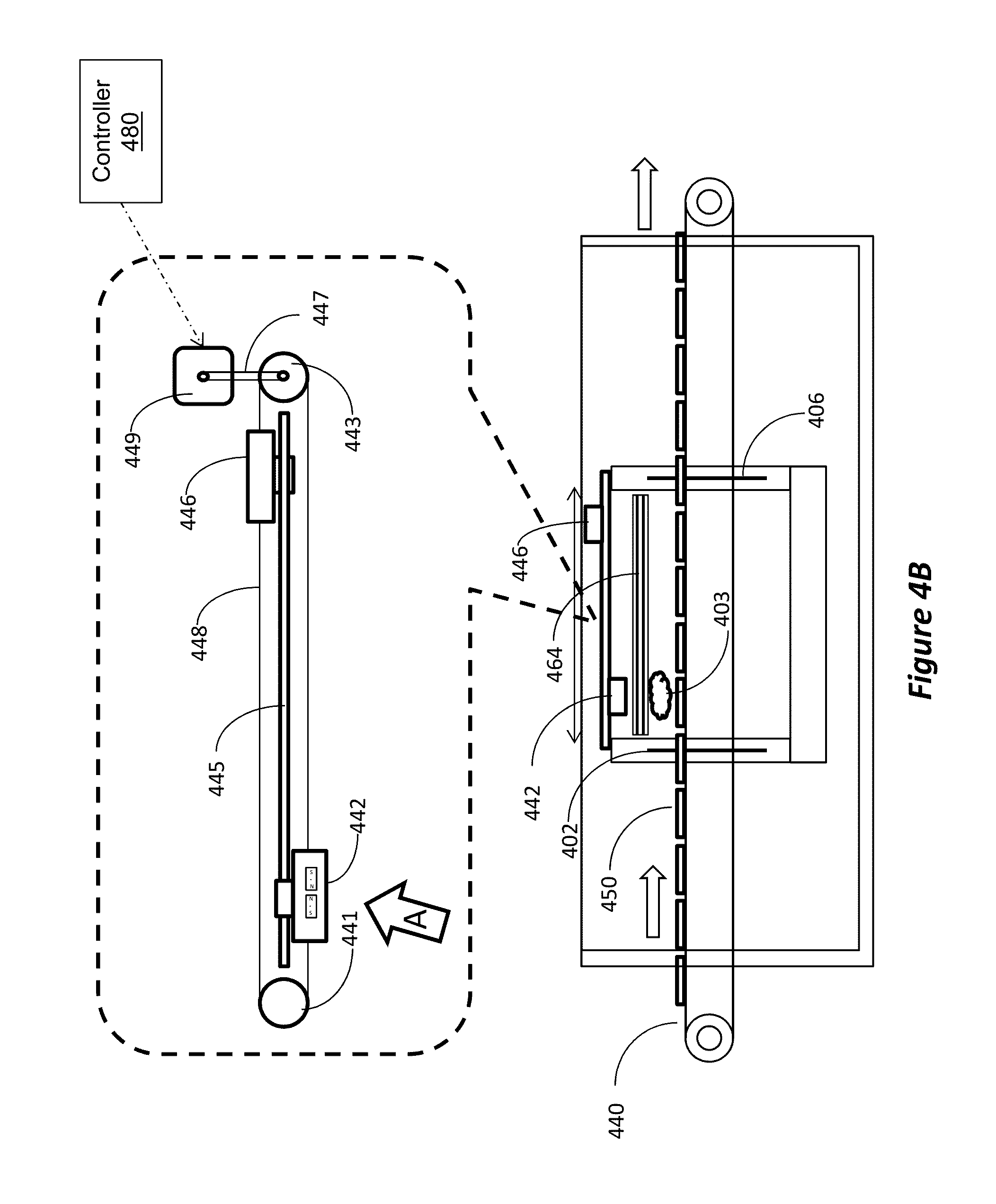
[0031]Embodiments of the inventive sputtering system will now be described with reference to the drawings. Different embodiments may be used for processing different substrates or to achieve different benefits, such as throughput, film uniformity, target utilization, etc. Depending on the outcome sought to be achieved, different features disclosed herein may be utilized partially or to their fullest, alone or in combination, balancing advantages with requirements and constraints. Therefore, certain benefits will be highlighted with reference to different embodiments, but are not limited to the disclosed embodiments.

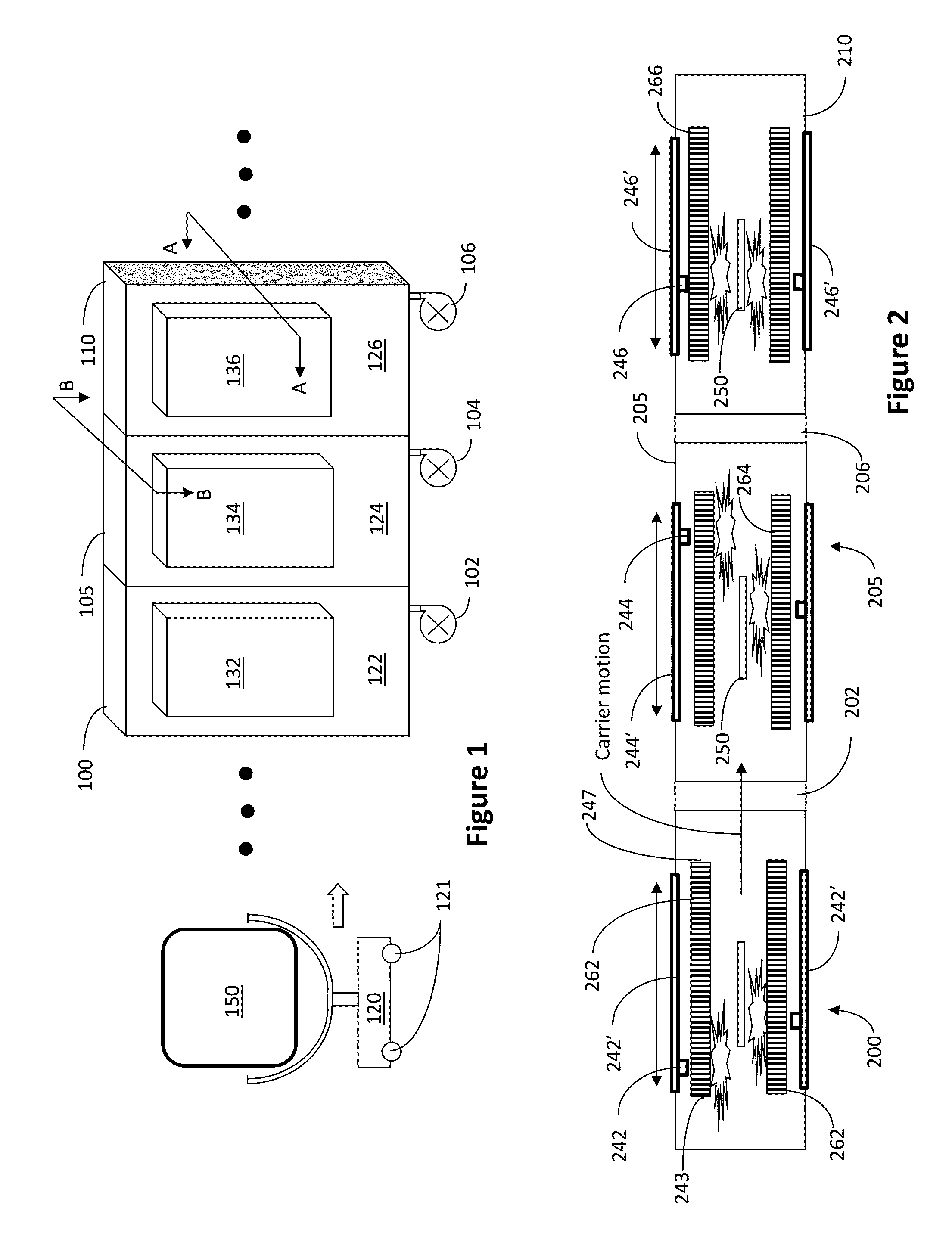
[0032]FIG. 1 illustrates part of a system for processing substrates using sputtering magnetron, according to one embodiment. In FIG. 1, three chambers, 100, 105 and 110, are shown, but the three dots on each side indicate that any number of chambers may be used. Also, while here three specific chambers are shown, it is not necessary that the chamber arrangement shown here...


PUM

PropertyMeasurementUnit
thicknessaaaaaaaaaa
speedaaaaaaaaaa
speedaaaaaaaaaa

Abstract

A system for depositing material from a target onto substrates, comprising a processing chamber; a sputtering target having length L and having highly magnetic sputtering material provided on front surface thereof a magnet assembly operable to reciprocally scan across the length L in close proximity to rear surface of the target and the magnet assembly comprises: a back plate made of magnetic material; a first group of magnets arranged in a single line central to the back plate and having a first pole positioned to face the rear surface of the target; and, a second group of magnets provided around periphery of the back plate so as to surround the first group of magnets, the second group of magnets having a second pole, opposite the first pole, positioned to face the rear surface of the target.

Description

RELAYED APPLICATIONS[0001]This application is a continuation-in-part of U.S. application Ser. No. 14 / 185,867, filed on Feb. 20, 2014, entitled “Sputtering System And Method Using Counterweight,” which is a continuation-in-part of U.S. application Ser. No. 13 / 667,976, filed on Nov. 2, 2012, entitled “Linear Scanning Sputtering System and Method,” which claims priority benefit from U.S. Provisional Application Ser. No. 61 / 556,154, filed on Nov. 4, 2011, entitled “Linear Scanning Sputtering System and Method,” the disclosures of which are incorporated herein by reference in their entirety.BACKGROUND[0002]1. Field[0003]This application relates to sputtering systems, such as sputtering systems used to deposit thin films on substrates during the fabrication of integrated circuits, solar cells, flat panel displays, etc.[0004]2. Related Arts[0005]Sputtering systems are well known in the art. An example of a sputtering system having a linear scan magnetron is disclosed in U.S. Pat. No. 5,873...

Claims


Application Information

Patent Timeline
Patent Type & Authority Applications(United States)
IPC IPC(8): H01J37/34
CPCH01J37/3455H01J37/3452H01J37/3426C23C14/35C23C14/56G11B5/851H01F41/183H01J37/3405H01J37/3408H01J37/3417H01J37/3435H01J37/347H01J37/32779H01J37/32899
Inventor BROWN, DAVID WARDBLUCK, TERRY
Owner INTEVAC
Why Eureka
Eureka Blog
Learn More