Eureka AIR delivers breakthrough ideas for toughest innovation challenges, trusted by R&D personnel around the world.

ITO conducting film glass plate sputtering cavity structure

A sputtering chamber and conductive film technology, applied in the field of ITO conductive film glass plate sputtering chamber structure, can solve the problems of substrate scratches, inability to fix the substrate, and waste of the remaining amount in the middle area of ​​the target, so as to avoid scratches Spend and damage, improve target utilization, and improve the effect of utilization

Pending Publication Date: 2022-05-13
凯盛信息显示材料(洛阳)有限公司
View PDF1 Cites 0 Cited by
  • Summary
  • Abstract
  • Description
  • Claims
  • Application Information

AI Technical Summary

Problems solved by technology

However, the structure of the magnetron sputtering cavity still has the following disadvantages: (1) The magnetic field lines are fixed during sputtering, pointing from the magnetic poles on both sides to the middle magnetic pole. After being sputtered, a lot of remaining amount in the middle area of ​​the target is wasted, resulting in low target utilization; (2) Since the surface of the inner circular surface is a round hole, and there are many gaps between the round holes, so that the atomic Or the molecular target falls on the gap between the round holes, and cannot be deposited on the substrate to form a thin film; (3) the substrate cannot be completely fixed on the heater with the base pressure ring, so that the substrate cannot be completely fixed on the heater. Sliding on the surface may scratch or even damage the surface of the substrate

Method used


Image

  • ITO conducting film glass plate sputtering cavity structure
  • ITO conducting film glass plate sputtering cavity structure
  • ITO conducting film glass plate sputtering cavity structure

Examples


Embodiment

[0024] see Figure 1 to Figure 6 , the present invention provides a technical solution:

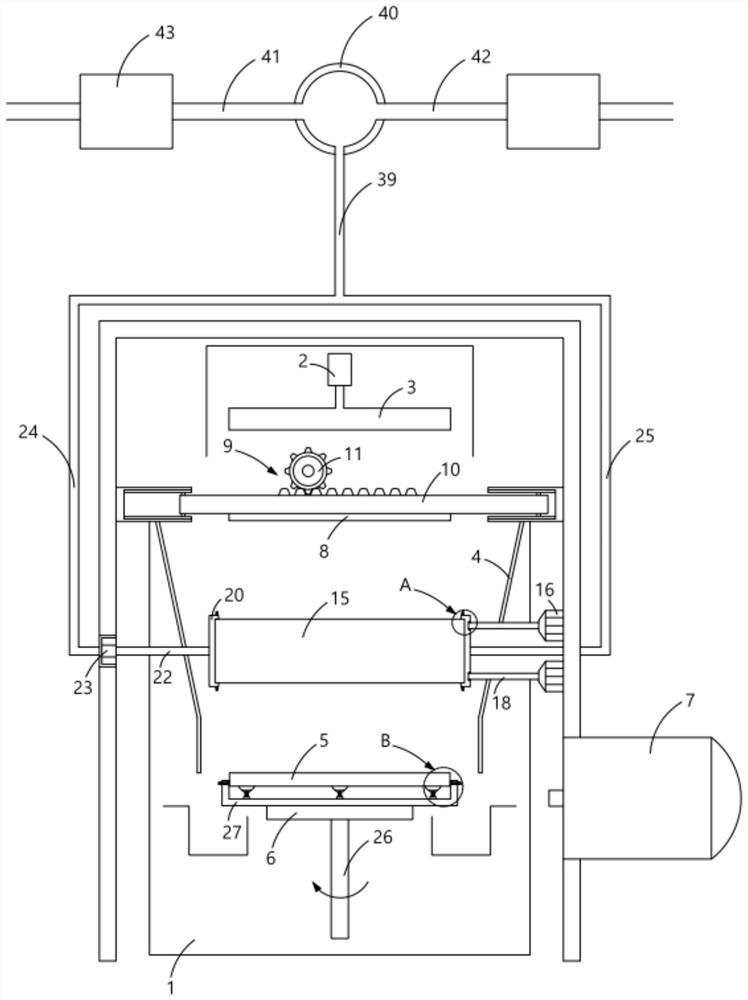
[0025] A kind of ITO conductive film glass plate material sputtering cavity structure, such as figure 1 As shown, it includes a cavity 1, a driving device 2 and a magnetic member 3 installed on the upper part of the cavity 1, a guard plate 4, a substrate 5 and a target 8 installed in the cavity 1, and a The cryopump 7 on the side wall of the body 1, the driving device 2 is fixedly connected to the magnetic part 3, the guard plate 4 is installed between the substrate 5 and the target 8, and the substrate 5 is generally calcium-based or Silicon boron base, the target material 8 is indium and tin metal. In order to improve the utilization rate of the target, the cavity structure also includes a transmission mechanism 9 that drives the target 8 to move left and right. The transmission mechanism 9 includes a rack 10 and a gear 11 meshing with the rack 10, such as Figure 4 As shown, the tar...


PUM


Abstract

The invention provides an ITO conducting film glass plate sputtering cavity structure which comprises a cavity, a driving device and a magnetic part which are installed on the upper portion of the cavity, a protection plate, a substrate and a target which are installed in the cavity and a low-temperature pump installed on the side wall of the cavity, the driving device is fixedly connected with the magnetic part, the protection plate is installed between the substrate and the target, and the low-temperature pump is installed on the side wall of the cavity. The cavity structure further comprises a transmission mechanism for driving the target material to move left and right, the transmission mechanism comprises a rack and a gear meshed with the rack, and the target material is fixedly connected with the side opposite to the rack. By installing the transmission mechanism, the utilization rate of the target material is improved, and by installing the vibration motor, the utilization rate of the target material and the ITO glass coating efficiency are further improved; the groove body is formed in the heating body, the supporting device is mounted on the groove body, and the fixing devices are mounted on the two sides of the heating body, so that the completeness of the substrate can be protected while the substrate is completely fixed, and the substrate is prevented from being scratched and damaged by fixing equipment.

Description

technical field [0001] The invention relates to the field of semiconductor process technology detection, in particular to a sputtering chamber structure of an ITO conductive film glass plate. Background technique [0002] Magnetron sputtering is mainly used for the preparation of thin films of metals and metal compounds. It is widely used in the semiconductor field because of its high coating efficiency and good adhesion. Magnetron sputtering bombards the surface of the cathode target with ionized inert gas ions through the joint action of electric field and magnetic field, so that the target is sputtered in the form of atoms or molecules, and deposited on the substrate to form a thin film. There are a lot of magnetron sputtering cavity structures in the prior art, for example, the application publication number is CN111254403A, a magnetron sputtering cavity that improves the uniformity of metal oxide films. The gas distribution device and the rotating shaft effectively sol...

Claims


Application Information

Patent Timeline
IPC IPC(8): C23C14/35C23C14/08C23C14/50
CPCC23C14/35C23C14/3407C23C14/086C23C14/505
Inventor 黄茜茜吕明泽朱汪根周道均汪旭东陈杰
Owner 凯盛信息显示材料(洛阳)有限公司
Why Eureka
Eureka Blog
Learn More