Motor Pylons For A Kite And Aiborne Power Generation System Using Same

Inactive Publication Date: 2013-08-29
MAKANI TECH LLC
View PDF3 Cites 55 Cited by
  • Summary
  • Abstract
  • Description
  • Claims
  • Application Information

AI Technical Summary

Benefits of technology

[0006]A motor pylon system adapted for use with an airborne power generations system is disclosed. The pylons may support turbine driven generators for wind based electrical power generation which also function as electric motors i

Problems solved by technology

However, take-off and landing of such kites can present difficulties, as th

Method used


Image

  • Motor Pylons For A Kite And Aiborne Power Generation System Using Same
  • Motor Pylons For A Kite And Aiborne Power Generation System Using Same
  • Motor Pylons For A Kite And Aiborne Power Generation System Using Same

Examples


Embodiment Construction

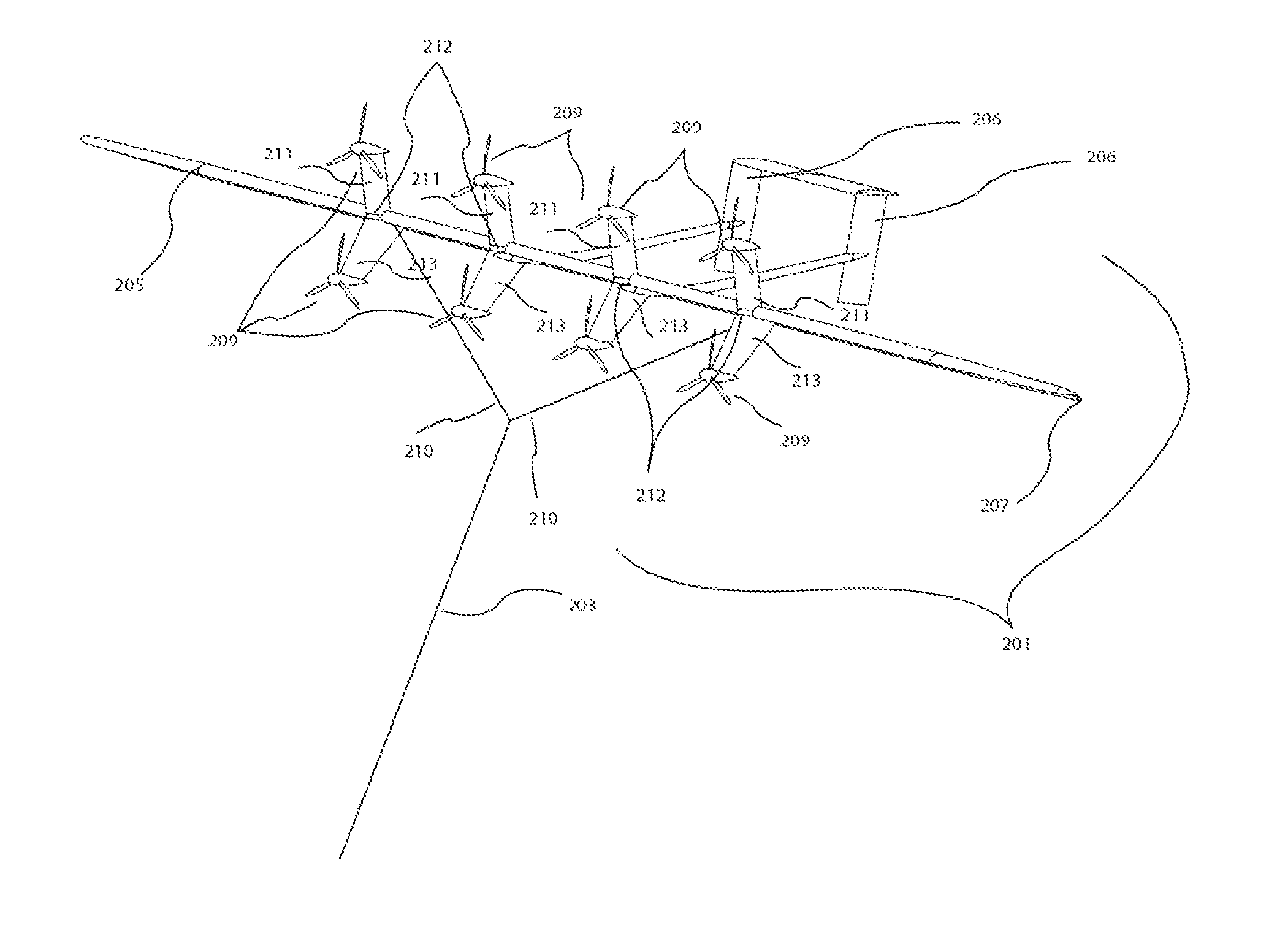
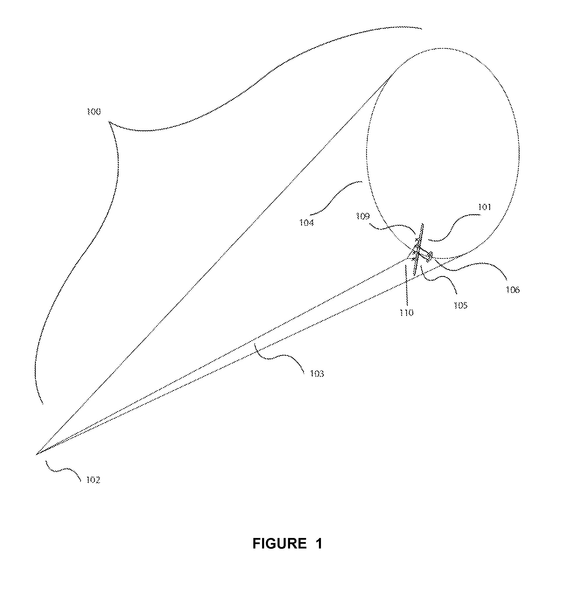
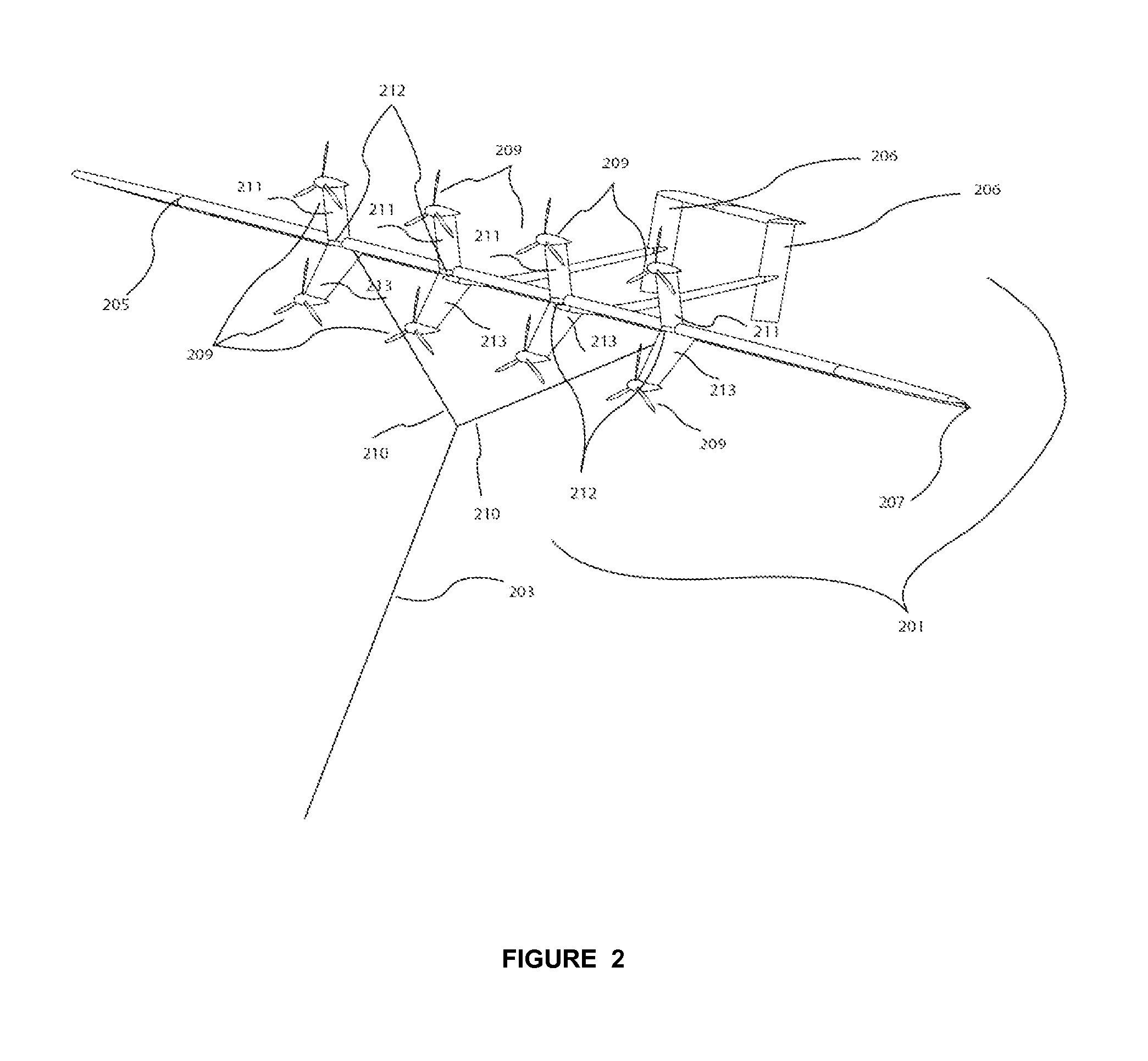
[0017]A motor pylon design for a kite system is disclosed. A kite system comprising motors or motor / generators may be used for a number of purposes. For example, a kite system comprising rotors and motor / generators might be used for extraction of power from the wind, might be used for towing of a vehicle, might be used for surveillance, or might be used as a communications relay. A kite system of this type can be launched and landed from a ground station in a hovering mode of flight, in which the kite hovers under thrust from on-board rotors, while the tether attaching the kite is reeled in or out from the ground station. The on-board rotors, as referred to herein, may be adapted for dual function. When providing thrust, the rotors are viewed as motor driven propellers. When being used to convert wind energy into electrical energy, the rotors are viewed as turbine driven generators. When operating, the kite either flies stationary in the wind, in the matter of a traditional kite, or...


PUM


Abstract

A motor pylon system adapted for use with an airborne power generations system is disclosed. The pylons may support turbine driven generators for wind based electrical power generation which also function as electric motors in some aspects. The pylons may be designed to provide side force useful for turning a tethered flying wing flying in a circular cross wind flight path. The pylons may be designed to minimize air flow disruptions over the main wing.

Description

CROSS REFERENCE TO RELATED APPLICATIONS[0001]This application claims priority to U.S. Provisional Patent Application No. 61 / 582,408 to Vander Lind et al., filed Jan. 2, 2012, which is hereby incorporated by reference in its entirety.BACKGROUND[0002]1. Field of the Invention[0003]The present invention relates to a system and method of flying tethered flying vehicles.[0004]2. Description of Related Art[0005]Crosswind kite systems comprising tethered wings (kites) can extract useful power from the wind for purposes such as, for example, generating electricity, lifting or towing objects or vehicles, etc. To provide or use consistent power, it may be desired to fly the kite in repeating trajectories (i.e., a limit cycle). It may also be desired to maintain the kite aloft and flying consistent trajectories during a large range of environmental conditions such as high wind speeds, large gusts, turbulent air, or variable wind conditions. However, take-off and landing of such kites can prese...

Claims


Application Information

Patent Timeline
IPC IPC(8): B64D27/26
CPCB64C31/06B64D27/24Y02E10/70B64D27/26Y02T50/62F03D5/00F03D9/25F03D13/20Y02E10/72Y02E10/728Y02T50/60
Inventor VANDER LIND, DAMONSINHA, PRANAY
Owner MAKANI TECH LLC
Why Eureka
Try Eureka