Energy extraction device, group of energy extraction devices and operating methods

a technology of energy extraction device and energy extraction method, which is applied in the direction of positive displacement liquid engine, electric generator control, fluid coupling, etc., can solve the problems of compromising the efficiency of power generation, consuming a significant amount of power independently, and typical electrical generators consuming a significant amount of power. , to achieve the effect of reducing the efficiency of power receipt, reducing the efficiency of energy uptake, and efficient energy receip

Inactive Publication Date: 2013-08-29
MITSUBISHI HEAVY IND LTD
View PDF5 Cites 44 Cited by
  • Summary
  • Abstract
  • Description
  • Claims
  • Application Information

AI Technical Summary

Benefits of technology

[0017]By allowing the rate of the displacement of working fluid by the at least one hydraulic pump and the at least one hydraulic motor to be varied relative to each other, for at least a period of time, so that the total amount of working fluid displaced into the high pressure manifold by the at least one pump is different to the total amount of working fluid displaced from the high pressure manifold by the at least one motor, power output (through the hydraulic motor) is decoupled, to at least some extent, from power input. Accordingly, individual energy extraction devices according to the first aspect of the invention are externally controllable to at least some extent, to enable power output to be varied without compromising (and typically without changing) power input. This is particularly effective when a plurality of individual energy extraction devices according to the first aspect of the invention are controlled in concert to smooth their combined power output or to achieve other intended effects. Similarly, individual energy extraction devices according to the first aspect of the invention can be better prepared for predicted future variations in the rate of energy flow from the renewable energy source. For example, the rate of rotation of a wind turbine can be varied (by varying the rate of displacement of working fluid by the hydraulic pump) or the torque of a wind turbine can be varied (as the torque is a function of the pressure of working fluid in the high pressure manifold, which increases when more fluid is displaced by the at least one hydraulic pump than by the at least one hydraulic motor).
[0074]In embodiments where the high pressure manifold of each energy extraction device is in communication with a respective working fluid receptacle, the method may comprise predicting a temporary change in the amount of energy from the energy flow which will be received by a group of one or more energy extraction devices and selecting the control signals to the respective group of one or more energy extraction devices such as to cause the group of one or more energy extraction devices to reduce the amount of working fluid stored in their respective working fluid receptacles in advance of (at least the peak of) the predicted temporary change in the amount of energy to be received.

Problems solved by technology

It is known to use electrical or other storage means to smooth the output from a group of WTGs but this can be expensive.
This necessarily involves reducing the power received by WTGs to significantly below the maximum amount of power which they could receive, at least some of the time, thereby compromising the efficiency of power generation.
In the case of a WTG or other energy extraction device which generates electrical power for an electricity grid using an electrical generator, a significant amount of power may be lost due to the operation of the electrical generator, rather than transmitted to the electricity grid.
Typical electrical generators consume a significant amount of power independently of their rate of rotation or field current due to so-called ‘winding losses’.
These losses can be substantial and it is known to provide a wind turbine with two electricity generators and to periodically switch off one of the electricity generators when power output drops below 50% of maximum capacity.
However, this leads to step changes in power output.
However, wind turbines typically operate in isolation and it is difficult for an isolated wind turbine to predict future wind speed.

Method used


Image

  • Energy extraction device, group of energy extraction devices and operating methods
  • Energy extraction device, group of energy extraction devices and operating methods
  • Energy extraction device, group of energy extraction devices and operating methods

Examples


Embodiment Construction

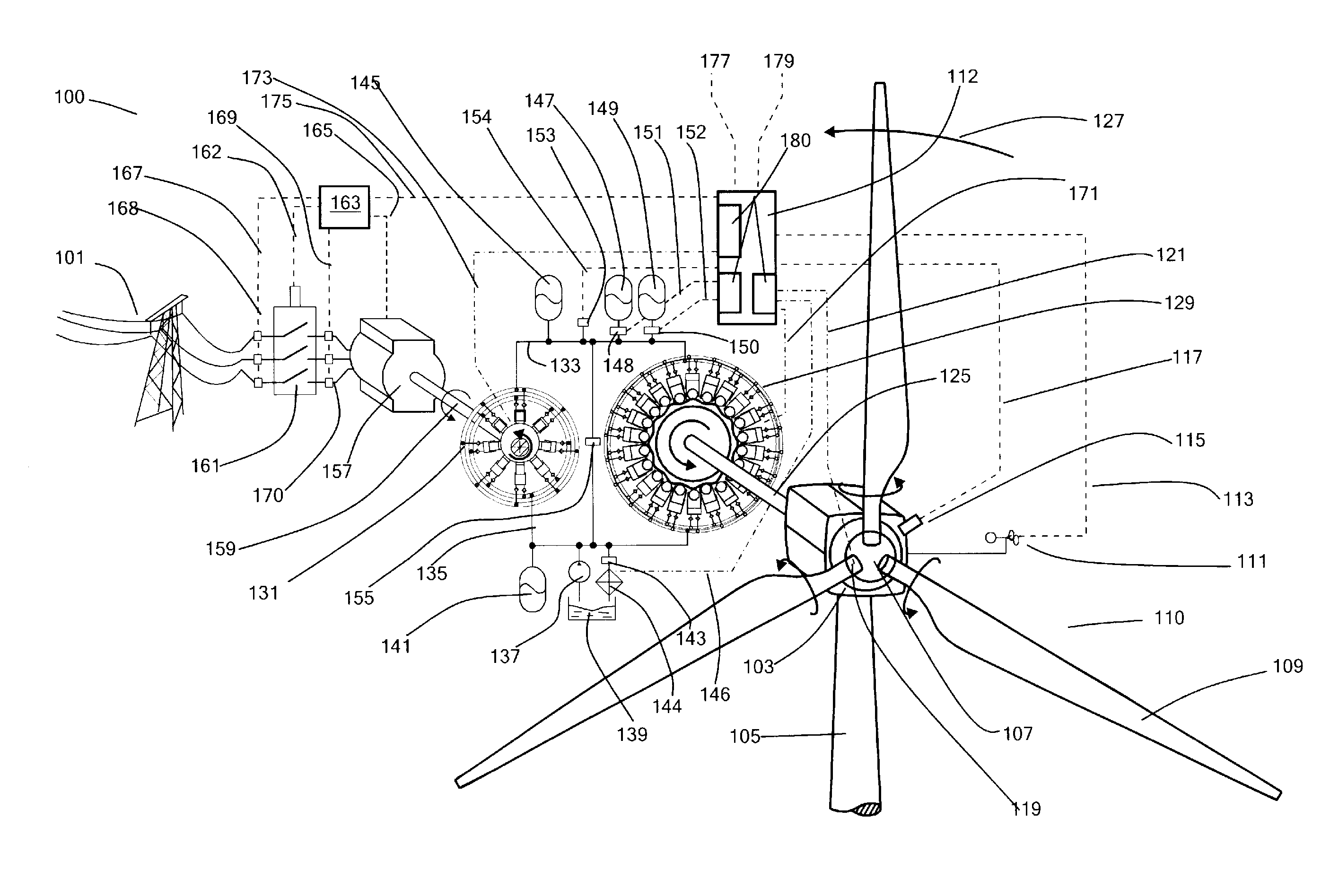
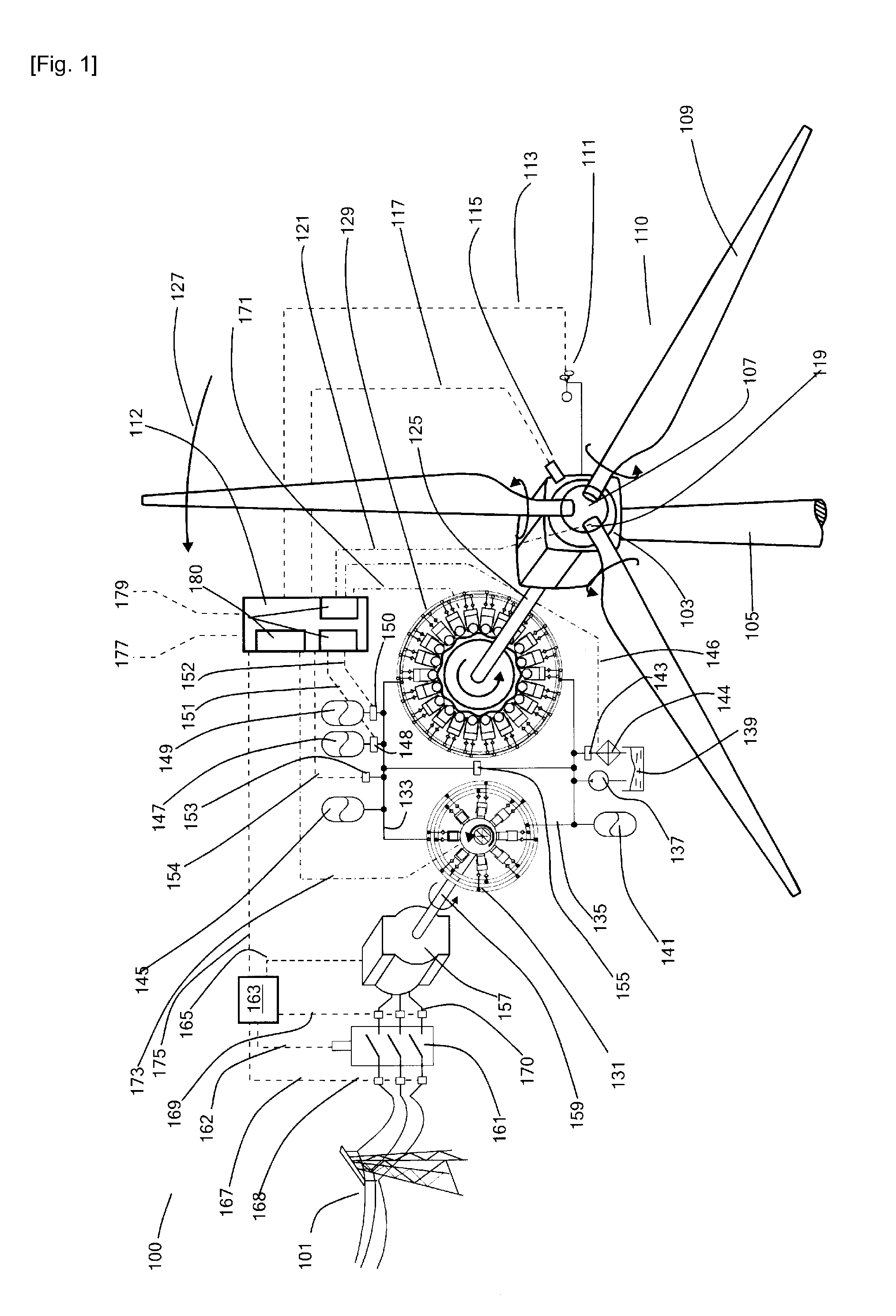
[0087]FIG. 1 illustrates an example embodiment of the invention in the form of a Wind Turbine Generator (WTG, 100), functioning as the energy extraction device, and connected to an electricity network (101). The WTG comprises a nacelle (103) rotatably mounted to a tower (105) and having mounted thereon a hub (107) supporting three blades (109) known collectively as the rotor (110). An anemometer (111) attached externally to the nacelle provides a measured wind speed signal (113) to a controller (112). A rotor speed sensor (115) at the nacelle provides the controller with a rotor speed signal (117, representative of the current rotation rate of the rotating shaft). In the example system the angle of attack of each of the blades to the wind can be varied by a pitch actuator (119), which exchanges pitch actuation signals and pitch sensing signals (121) with the controller. The invention could be applied to a WTG without a pitch actuator.

[0088]The hub is connected directly to a pump (12...


PUM


Abstract

A wind turbine generator (100), or other energy extraction device, has a hydraulic circuit comprising a hydraulic pump (129) driven by a rotating shaft (125) and a hydraulic motor (131) driving an electricity generator (157), or other load. A high pressure manifold (133) extending between the pump and motor is in communication with an accumulator (145, 147, 149). A controller receives a control signal and regulates the displacement of working fluid by the hydraulic pump and the hydraulic motor relative to each other. Thus, power input through the rotating shaft and output to the load can be decoupled for at least a period of time and the energy output of energy extraction device can be varied, for example to smooth the total power output to an electricity grid (101), without compromising power input. A group of energy extraction devices can be controlled in concert to maximise power input while providing smooth power output. Individual electricity generators in different energy extraction devices can be switched on and off in concert to provide smooth power output while benefiting from the reduced energy losses that can be obtained by switching off electricity generators where possible.

Description

TECHNICAL FIELD[0001]The invention relates to the field of energy extraction devices for extracting energy from renewable energy sources, for example, wind turbines, and also to groups of energy extraction devices, such as wind farms. Energy extraction devices according to the invention have a hydraulic transmission including a hydraulic pump driven by a rotating shaft and a hydraulic motor driving a load, such as an electrical generator.BACKGROUND ART[0002]The technical background to the invention will now be discussed with reference to energy extraction devices which are wind turbine generators (WTGs), for extracting energy from the wind, however the same principles will apply to other types of energy extraction device, for extracting energy from other renewable energy sources.[0003]Energy extraction devices for extracting energy from a renewable energy source are typically configured to optimise the amount of power which they extract. However, there are many additional factors wh...

Claims


Application Information

Patent Timeline
Patent Type & Authority Applications(United States)
IPC IPC(8): F03D9/00
CPCF03D9/001F04B17/02F05B2260/406F03D11/02F04B1/053F03D9/005F05B2240/96Y02E10/722Y02E10/725Y02E60/17F03C1/26F03D9/28F03D15/00F03D9/257Y02E10/72Y02E60/16Y02P80/10F03D15/20
Inventor CALDWELL, NIALLDUMNOV, DANIILFIELDING, MICHAELLAIRD, STEPHENSTEIN, UWETAYLOR, JAMIE
Owner MITSUBISHI HEAVY IND LTD
Why Eureka
Try Eureka