Adaptation of control signaling transmissions to variations in respective resources

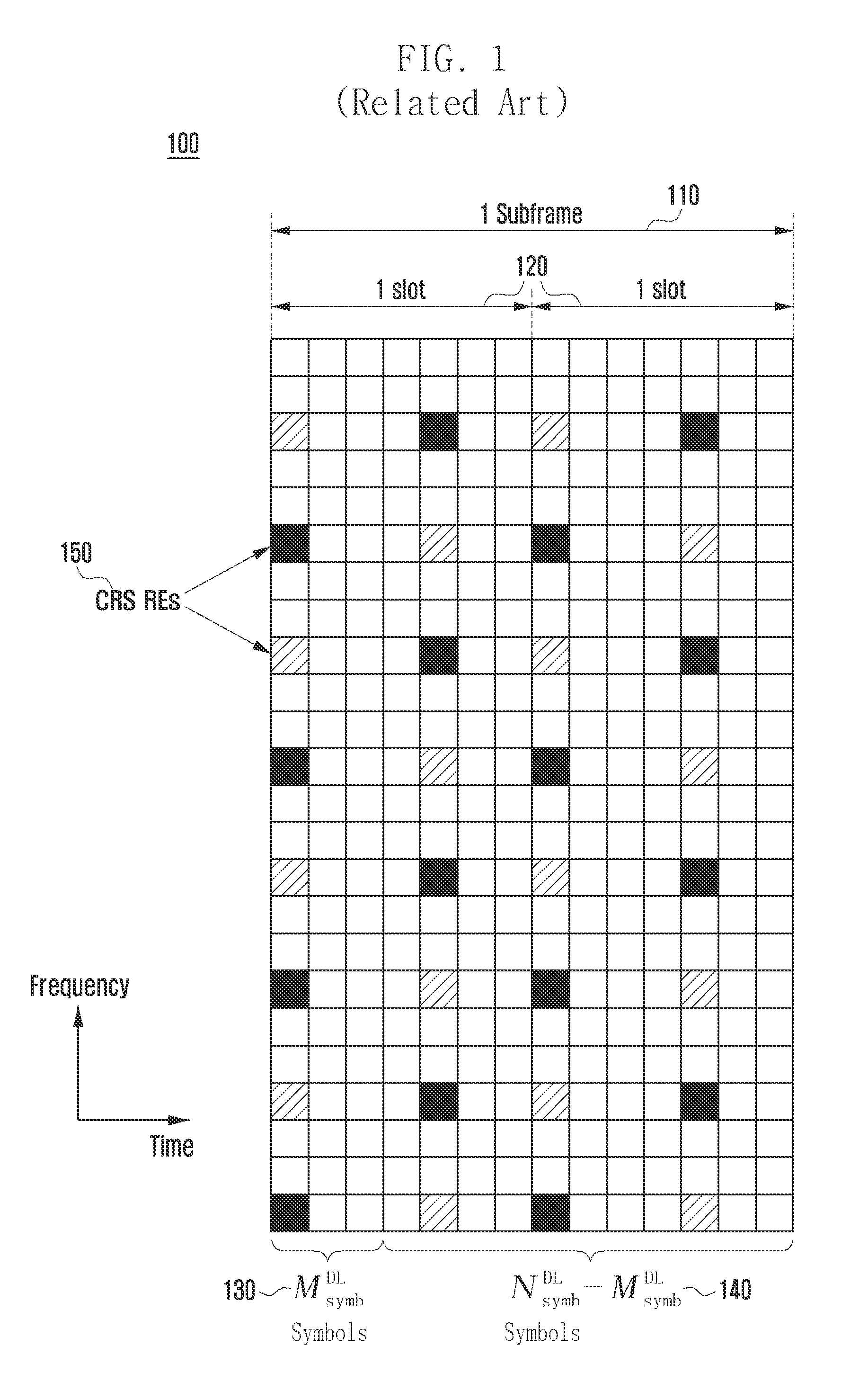
a control signaling and resource technology, applied in the field of wireless communication systems, can solve the problems of limiting the pdcch capacity of the dl control region, unable to support interference coordination in the frequency domain, and unable to extend the legacy dl control region to more than m/symb/sup>sup>dl/sup>=3 subframe symbols,

Active Publication Date: 2013-08-29
SAMSUNG ELECTRONICS CO LTD
View PDF7 Cites 74 Cited by
  • Summary
  • Abstract
  • Description
  • Claims
  • Application Information

AI Technical Summary

Benefits of technology

[0045]In accordance with still another aspect of the present invention, an apparatus for receiving a PDCCH transmitted by a base station in REs of a set of PRBs, a single PRB of the set of PRBs comprising of a number of frequency sub-carriers over a TTI, using an aggregation level of L CCEs in one of M(L) candidate PDCCH locations is provided. The apparatus includes a comparator configured to determine whether the number of REs in a PRB available for transmitting PDCCHs is smaller than a predetermined number, a

Problems solved by technology

This configuration limits PDCCH capacity of the DL control region and cannot support interference coordination in the frequency domain among PDCCH transmissions from different NodeBs.
A direct extension of the legacy DL control region to more than MsymbDL=3 subframe symbols is not possible at least due to the requirement to support legacy UEs which are not aware of nor support such an extension.
However, in many cases, for example in heterogeneous networks, a UE may not be able to reliably receive PDCCHs, or PDCCHs may not exist.
Moreover, for networks where a macro-NodeB and pico-NodeBs share a same cell identity, the capacity of the legacy CSS may not be sufficient to convey TPC commands to all UEs in the coverage area of the macro-NodeB.
Although UE1, UE2, and UE3 ar

Method used


Image

  • Adaptation of control signaling transmissions to variations in respective resources
  • Adaptation of control signaling transmissions to variations in respective resources
  • Adaptation of control signaling transmissions to variations in respective resources

Examples


Embodiment Construction

[0064]The following description with reference to the accompanying drawings is provided to assist in a comprehensive understanding of exemplary embodiments of the invention as defined by the claims and their equivalents. It includes various specific details to assist in that understanding but these are to be regarded as merely exemplary. Accordingly, those of ordinary skill in the art will recognize that various changes and modifications of the embodiments described herein can be made without departing from the scope and spirit of the invention. In addition, descriptions of well-known functions and constructions may be omitted for clarity and conciseness.

[0065]The terms and words used in the following description and claims are not limited to the bibliographical meanings, but, are merely used by the inventor to enable a clear and consistent understanding of the invention. Accordingly, it should be apparent to those skilled in the art that the following description of exemplary embod...


PUM


Abstract

A method and an apparatus for a User Equipment (UE) to receive a first type of a Physical Downlink Control CHannel (PDCCH) or a second type of a PDCCH in a Transmission Time Interval (TTI) are provided whereby the first type of PDCCH and the second type of PDCCH convey respective Downlink Control Information (DCI) formats containing Cyclic Redundancy Check (CRC) bits scrambled with a Radio Network Temporary Identifier (RNTI). The method includes receiving by the UE a first bitmap associated with a number of TTIs equal to the first bitmap size, wherein each element of the first bitmap indicates whether a TTI is of a first type or of a second type, decoding by the UE only PDCCH of the first type if the TTI is of the first type, and decoding by the UE only PDCCH of the second type if the TTI is of the second type.

Description

CROSS-REFERENCE TO RELATED APPLICATIONS[0001]This application claims the benefit under 35 U.S.C. §119(e) of U.S. Provisional Applications No. 61 / 603,903 which was filed in the United States Patent and Trademark Office on Feb. 27, 2012, and No. 61 / 704,791 which was filed in the United States Patent and Trademark Office on Sep. 24, 2012, the entire disclosure of each of which is hereby incorporated by reference.BACKGROUND OF THE INVENTION[0002]1. Field of the Invention[0003]The present invention is directed generally to wireless communication systems. More particularly, the present invention is related to the transmission and reception of physical downlink control channels.[0004]2. Description of the Art[0005]A communication system includes a DownLink (DL) that conveys transmission signals from transmission points such as Base Stations (BS or NodeBs) to User Equipments (UEs) and an UpLink (UL) that conveys transmission signals from UEs to reception points such as NodeBs. A UE, also co...

Claims


Application Information

Patent Timeline
IPC IPC(8): H04W72/04
CPCH04W72/042H04L5/0007H04L5/0076H04L5/0094H04L5/0055H04L5/0053H04B7/2612H04B7/2621H04J11/005H04W72/23H04W72/0446H04W88/02
Inventor PAPASAKELLARIOU, ARISJI, HYOUNGJU
Owner SAMSUNG ELECTRONICS CO LTD
Why Eureka
Try Eureka