A base plate for an ostomy appliance

a technology for ostomy and base plates, applied in medical preparations, surgery, medical science, etc., can solve the problems of irritating and sensitive skin area close to stoma, affecting the appearance of ostomy, so as to avoid the most uneven skin topography

Active Publication Date: 2013-08-29
COLOPLAST AS
View PDF15 Cites 27 Cited by
  • Summary
  • Abstract
  • Description
  • Claims
  • Application Information

AI Technical Summary

Benefits of technology

[0016]In one embodiment, the overlap is between 5 and 15 mm. This places the soft adhesive in a small distance away from the stoma, thereby avoiding the most uneven skin topography, as the area closest to the stoma often has the worst scar tissue as a result from e.g. sutures and frequent contact with effluents.

Problems solved by technology

It is a common problem for ostomates that the skin area close to stoma, also referred to as the peristomal area, is often irritated and sensitive.
The output is very aggressive and quickly irritates the skin.
Moreover, when the user is wearing a base plate for use in an ostomy device, either a one-piece or a two-piece device, then there is a high risk that the returning output comes into contact with the inner edge of the adhesive of the plate.
When in contact with the adhesive, the aggressive output will then erode the adhesive away.
In addition, seeing that sutures may have been used for securing the stoma during surgery or subsequent complications, the peristomal area may be scarred making it even more difficult to provide a seal between the skin and the adhesive wafer.
This can create small gaps between the skin and the base plate where the output may enter, thus creating a moist environment that further irritates the skin but also deteriorates the adhesive attachment between the adhesive and the skin resulting in leakage or even dislodging of the base plate.

Method used


Image

  • A base plate for an ostomy appliance
  • A base plate for an ostomy appliance
  • A base plate for an ostomy appliance

Examples


first embodiment

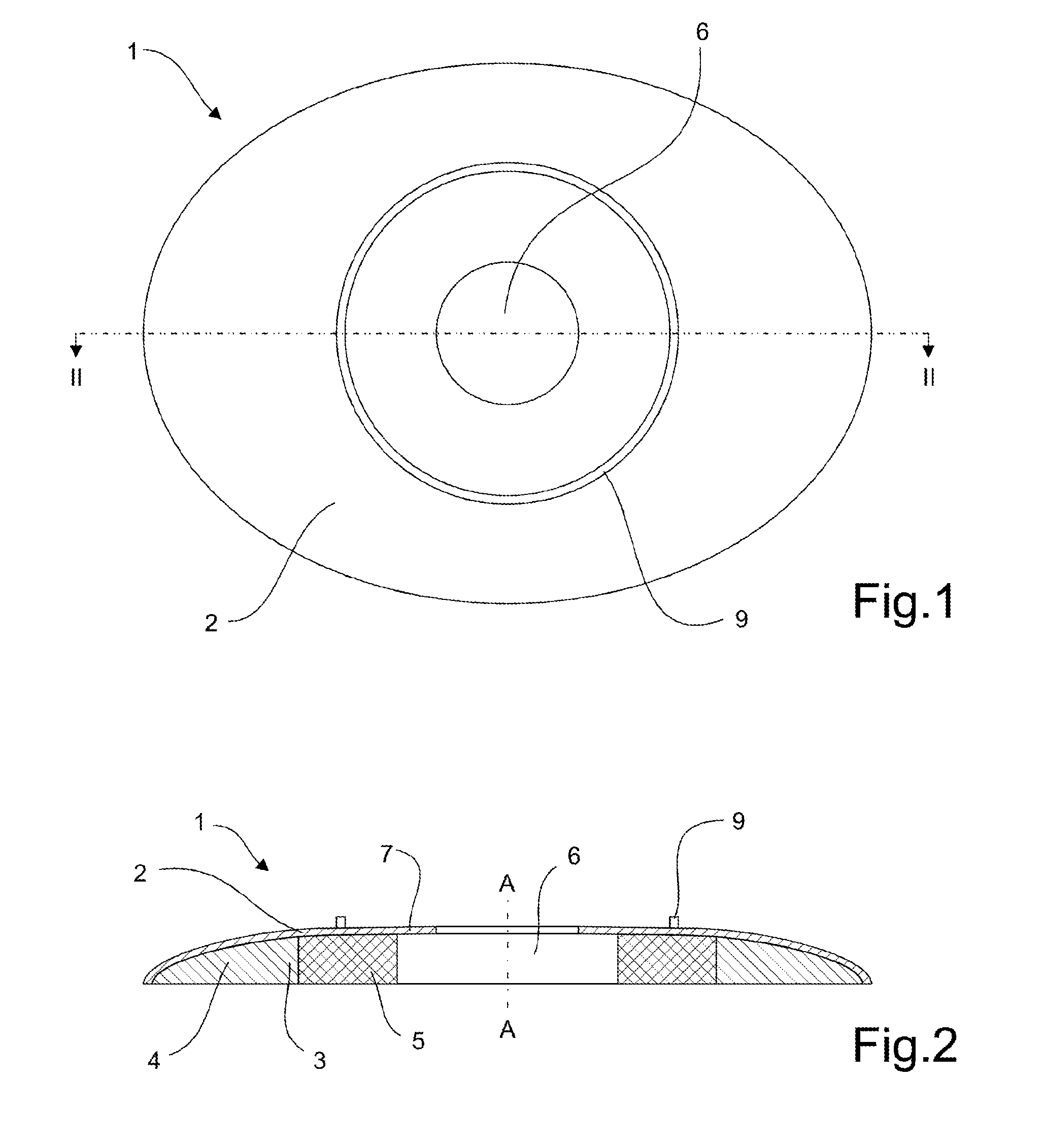
[0024]a base plate 1 is shown in FIGS. 1 and 2. The base plate has a cover layer in the form of a backing layer 2 whereon an adhesive layer 3 has been disposed.

[0025]The adhesive layer 3 is in the form of an outer adhesive 4, which is a high tack adhesive, and an inner adhesive 5. The inner adhesive encircles a through-going hole, which extends axially along axis A-A through the base plate. The inner adhesive and the backing layer whereon it is disposed form an inner area defining the through-going hole. The inner adhesive is softer than the outer adhesive, i.e. it will take the shape of the topography of the skin and thus provide a good seal to the skin.

[0026]The backing layer 2 extends beyond the adhesive layer 3 in a radial direction toward the through-going hole. This provides an overlap in the shape of an inner flange 7. The flange will function as a seal against the stoma and protect the adhesive layer from stomal output.

[0027]A coupling ring 9 is provided to which an ostomy b...

second embodiment

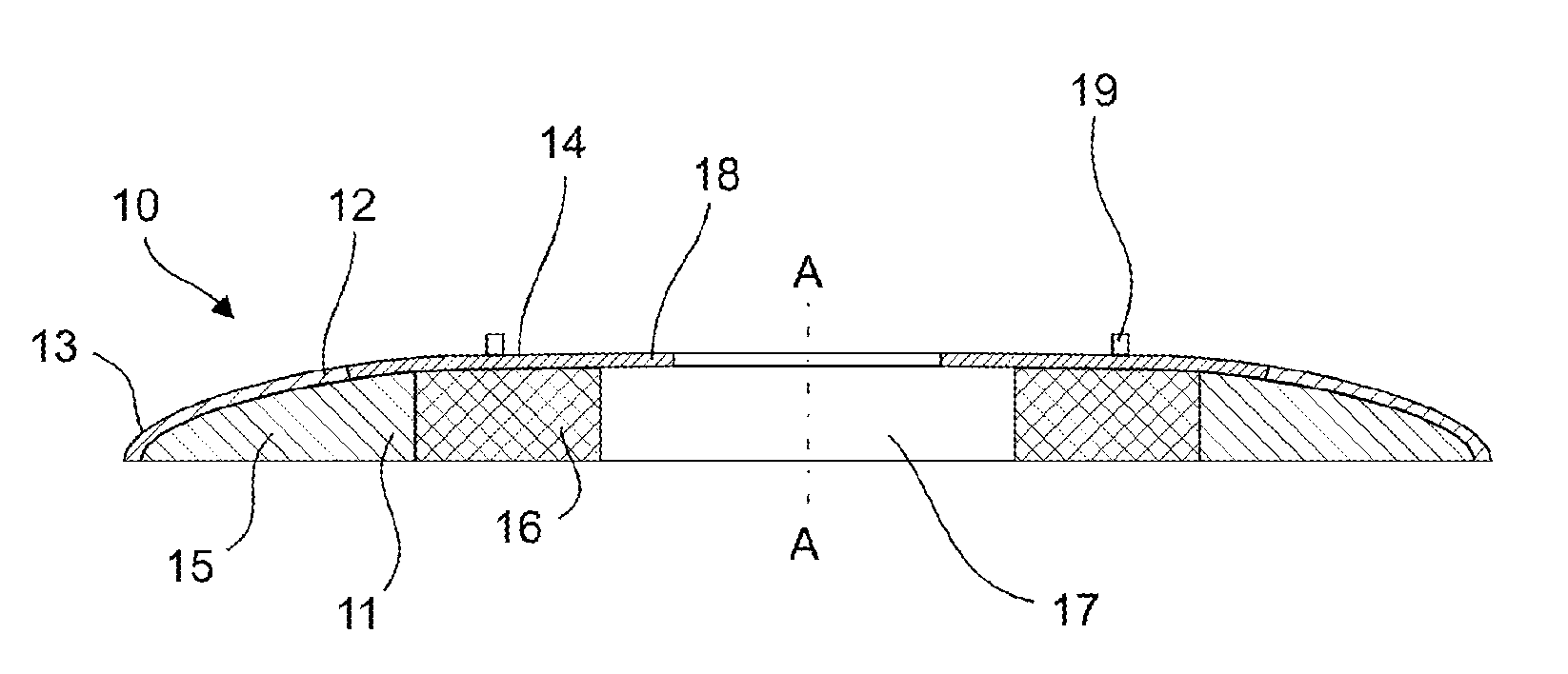
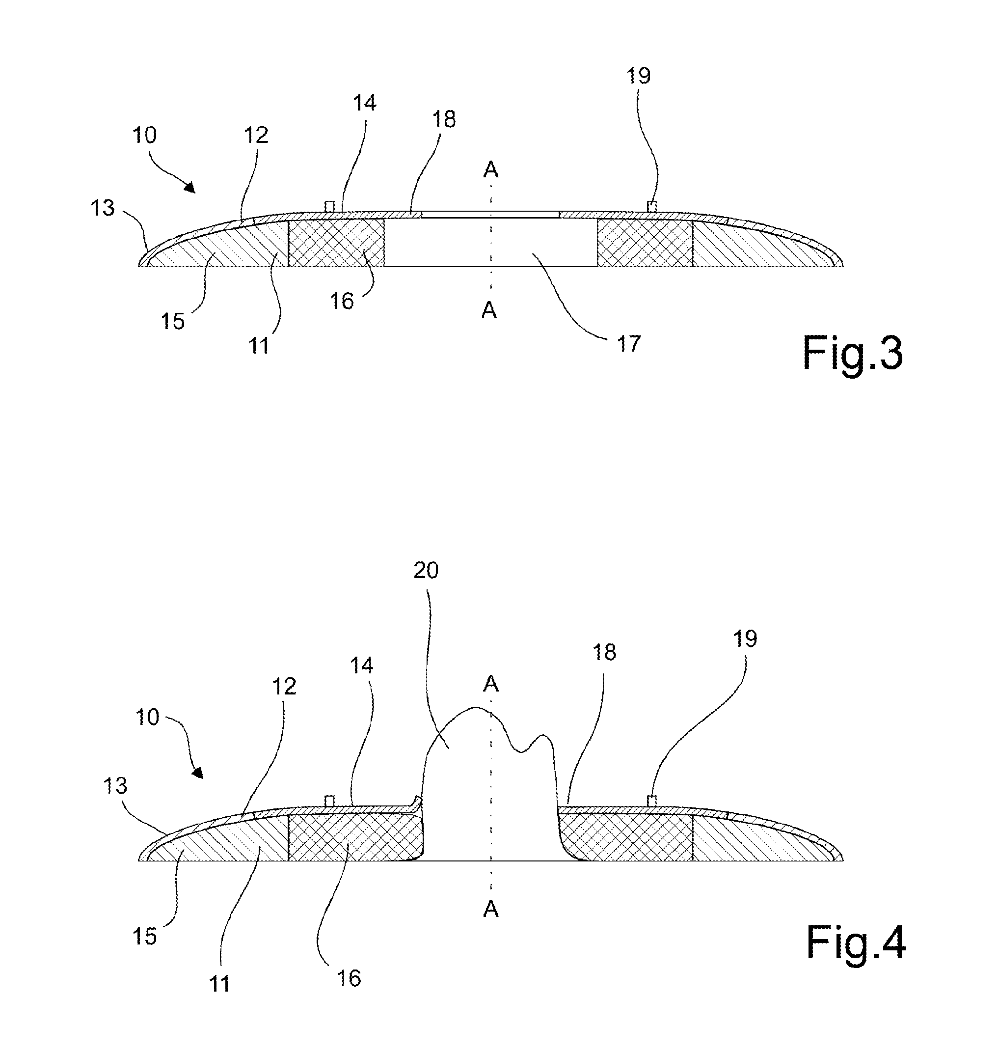
[0028]a base plate 10 is shown in FIG. 3. An adhesive layer 11 is disposed on a cover layer 12. The cover layer is formed by an outer backing layer 13 which encircles an inner foam layer 14. The adhesive layer is formed of an outer adhesive 15 which is disposed on the backing layer and an inner adhesive 16 which is disposed on the foam layer. As seen in the figure, there may be a small overlap, i.e. some of the outer adhesive may be arranged on the foam layer or vice versa.

[0029]A coupling ring 19 is provided to which an ostomy bag may be coupled. However, other coupling solutions may be used without deviating from the scope of the present invention.

[0030]The foam layer and the inner adhesive form an inner area defining a through-going hole 17 which extends axially through the base plate along axis A-A. Similar to the embodiment in FIGS. 1 and 2 the foam layer extends beyond the inner adhesive creating an overlap in the form of a flange 18. Seeing that the flange is formed of a foam...


PUM


Abstract

Disclosed is abase plate 1 for an ostomy collection device, comprising a cover layer 2 whereon an adhesive layer 3 is at least partly disposed. Immediately surrounding a through-going hole 6, the base plate has an inner area wherein the cover layer extends beyond the adhesive layer in a radial direction toward the through-going hole, thereby providing an overlap 7 protecting the adhesive material from contact with stomal output.

Description

TECHNICAL FIELD[0001]The present invention relates to an adhesive base plate for use with an ostomy appliance. In particular, the base plate is provided with means for preventing output from the stoma from coming into contact with the peristomal area.BACKGROUND[0002]It is a common problem for ostomates that the skin area close to stoma, also referred to as the peristomal area, is often irritated and sensitive. This is caused by stomal effluent, i.e. output from the stoma, running back from the stoma opening, along the outer surface of the stoma and into contact with the peristomal skin area.[0003]The output is very aggressive and quickly irritates the skin. Moreover, when the user is wearing a base plate for use in an ostomy device, either a one-piece or a two-piece device, then there is a high risk that the returning output comes into contact with the inner edge of the adhesive of the plate. When in contact with the adhesive, the aggressive output will then erode the adhesive away....

Claims


Application Information

Patent Timeline
Patent Type & Authority Applications(United States)
IPC IPC(8): A61F5/443
CPCA61F5/448A61F5/443A61F5/449A61L24/001A61L24/0036A61L24/046A61L2400/14
Inventor HANSEN, MICHAELISRAELSON, DORRIT DIANAEDVARDSEN, HENRIK
Owner COLOPLAST AS
Why Eureka
Try Eureka